DALI ballast variables
Every DALI ballast has a certain number of variables (parameters ) from which it is possible to read a variety of information or to modify individual parameters.
Name | Default value | Reset value | Valid range | Size | Comment |
|---|---|---|---|---|---|
? | 254 | 0, MIN LEVEL ... MAX LEVEL | 1 byte |
| |
254 | 254 | 1 ... 254 | 1 byte |
| |
254 | 254 | 0 ... 255 | 1 byte |
| |
PHYSICAL MIN LEVEL | PHYSICAL MIN LEVEL | PHYSICAL MIN LEVEL ... MAX LEVEL | 1 byte |
| |
254 | 254 | MIN LEVEL ... 254 | 1 byte |
| |
7 | 7 | 1 ... 15 | 1 byte |
| |
0 | 0 | 0 ... 15 | 1 byte |
| |
255 | No change | 0 ... 63, 255 | 1 byte |
| |
FF FF FF | FF FF FF | 00 00 00 ... FF FF FF | 3 bytes |
| |
FF FF FF | FF FF FF | 00 00 00 ... FF FF FF | 3 bytes |
| |
0 | 0 | 0 ... 255 | 1 byte |
| |
0 | 0 | 0 ... 255 | 1 byte |
| |
255 | 255 | 0 ... 255 | 1 byte |
| |
... | ... | ... | ... | ... |
|
255 | 255 | 0 ... 255 | 1 byte |
| |
???? ???? | 0?10 0??? | 0 ... 255 | 1 byte | read only | |
Manufacturer-dependent | Manufacturer-dependent | 0 ... 255 | 1 byte | read only | |
Manufacturer-dependent | Manufacturer-dependent | 0 ... 255 | 1 byte | read only | |
Manufacturer-dependent | Manufacturer-dependent | 1 ... 254 | 1 byte | read only |
?: Not specified
ACTUAL DIM LEVEL
This variable contains the power currently applying to the lamp.
The value can be read with the FB_DALIV2QueryActualLevel() block.
POWER ON LEVEL
When power is supplied to the ballast the lamp is driven to the level of power specified in the variable POWER ON LEVEL. This assumes that the DALI bus has already been supplied with power and is idle. The range of values available to POWER ON LEVEL is restricted by the two variables MIN LEVEL and MAX LEVEL.
The variable can be read with the FB_DALIV2QueryPowerOnLevel() block, and written with FB_DALIV2StoreDTRAsPowerOnLevel().
SYSTEM FAILURE LEVEL
If a fault occurs on the DALI bus (the idle voltage remains below the specified level for longer than 500 ms) then the lamp is driven to the power specified by the SYSTEM FAILURE LEVEL variable. If the variable contains 255 (mask) the lamp power will not change. The possible range is limited by MIN LEVEL and MAX LEVEL.
The variable can be read with the FB_DALIV2QuerySystemFailureLevel() block, and written with FB_DALIV2StoreDTRAsSystemFailureLevel().
MIN LEVEL / MAX LEVEL
The ballast internally restricts the value of the output power to the lamp by means of the MIN LEVEL and MAX LEVEL variables. The exceptions to this are power values of 0 (off) and 255 (mask).
FADE RATE
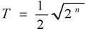
The FADE RATE specifies the rate at which changes are made (in steps per second) in the value of the lamp's power. This variable has an effect on the FB_DALIV2Up() and FB_DALIV2Down() commands. The absolute fade rate is not entered directly, but it is calculated according to the following formula:
|
|
T = absolute fade rate | |
n = value that is stored in the FADE RATE variable | |
|

The following values result:
n | absolute fade rate |
|---|---|
0 | Not permitted |
1 | 357,796 steps/s |
2 | 253.000 steps/s |
3 | 178,898 steps/s |
4 | 126,500 steps/s |
5 | 89,449 steps/s |
6 | 63,250 steps/s |
7 | 44,725 steps/s |
8 | 31,625 steps/s |
9 | 22,362 steps/s |
10 | 15,813 steps/s |
11 | 11,181 steps/s |
12 | 7,906 steps/s |
13 | 5,591 steps/s |
14 | 3,953 steps/s |
15 | 2.795 steps/s |
FADE TIME
The FADE TIME specifies the time allowed for the current lamp power to be changed to the requested value. In the case of a lamp that is switched off, the pre-heating and ignition time is not included in the fade time. The FB_DALIV2DirectArcPowerControl() and FB_DALIV2GoToScene() blocks are affected. The absolute fade time is not entered directly, but it is calculated according to the following formula:
|
|
T = absolute fade time | |
n = value that is stored in the FADE TIME variable | |
|
The following values result:
n | absolute fade time |
|---|---|
0 | < 0.707 s |
1 | 0,707 s |
2 | 1.000 s |
3 | 1,414 s |
4 | 2.000 s |
5 | 2,828 s |
6 | 4.000 s |
7 | 5,657 s |
8 | 8.000 s |
9 | 11,314 s |
10 | 16.000 s |
11 | 22,627 s |
12 | 32.000 s |
13 | 45,255 s |
14 | 64.000 s |
15 | 90.510 s |
SHORT ADDRESS
The short address is stored in this variable. A valid short address lies in the range between 0 and 63. The short address is regarded as having been deleted if 255 is written to the variable. The short address can be set with the FB_DALIV2SetShortAddress() and FB_DALIV2StoreDTRAsShortAddress() blocks. Calling the FB_DALIV2QueryMissingShortAddress() queries whether a ballast still does not have a short address.
SEARCH ADDRESS
The search address is only needed when assigning short addresses.
RANDOM ADDRESS
The random address, also called the long address, is specified by the manufacturer when the ballasts are supplied. The FB_DALIV2QueryRandomAddress() block can be used to read out the 3 bytes of the random address.
GROUP 0-7 / GROUP 8-15
16 groups exist within a DALI network. Any ballast can belong to one group, to several, or indeed to none. Commands that are to be sent to a group have an effect on all the ballasts that belong to that particular group. The FB_DALIV2QueryGroups() block reads both 8-bit variables and assembles them into a single 16 bit value. Each bit indicates whether the ballast belongs to a particular group.
SCENE 0-15
Each DALI ballast can store lamp power values for 16 different scenes. There is a value of the lamp power for every scene. If the command for calling up a scene (FB_DALIV2GoToScene()) is sent to one device, a group, or to all the devices (broadcast), then each of the affected lamps is set to the saved value. The output is limited by the values of MAX LEVEL, MIN LEVEL and PHYSICAL MIN LEVEL.
STATUS INFORMATION
The status information contains the most important items describing the status of a ballast. The 8-bit value can be read with the FB_DALIV2QueryStatus() block. The significance of the individual bits is defined as follows:
Bit | Description |
|---|---|
0 | Status of the ballast. 0: OK. |
1 | Lamp failure. 0: OK. |
2 | Lamp power on. 0: OFF. |
3 | Limit value error. 0: the most recently requested lamp power was either between MIN LEVEL and MAX LEVEL or was OFF. |
4 | Fading completed: 0: fading finished. 1: fading active. |
5 | Reset status. 0: No. |
6 | Missing short address. 0: No. |
7 | Power supply fault. 0: No, A reset, or a lamp power control command has been received since the most recent power up. |
VERSION NUMBER
VERSION NUMBER
The version number corresponds to the version number of the IEC standard in accordance with which the ballast was developed and manufactured. The version number can only be read, and is specified by the manufacturer of the ballasts. The major version (nMajorVersion) and the minor version (nMinorVersion) can each have a value in the range from 0 to 15 (4 bits).
DEVICE TYPE
DEVICE TYPE
The value can be read, for which the FB_DALIV2QueryDeviceType() block is used. The following device types are defined according to the IEC 62386 standard:
Value | Description |
|---|---|
0 | Standard device |
1 | Device for emergency lighting. |
2 | Device for discharge lamps. |
3 | Device for low-voltage halogen lamps. |
4 | Device for dimming bulbs. |
5 | Device for converting digital signals into DC signals. |
6 | Device for light emitting diodes (LEDs). |
7 | Switching function. |
8 | Device for colour/colour temperature control. |
PHYSICAL MIN LEVEL
PHYSICAL MIN LEVEL
The lowest physically possible lamp power level is stored by the manufacturer in the PHYSICAL MIN LEVEL variable. The value can only be read, for which the FB_DALIV2QueryPhysicalMinimumLevel() block is used.