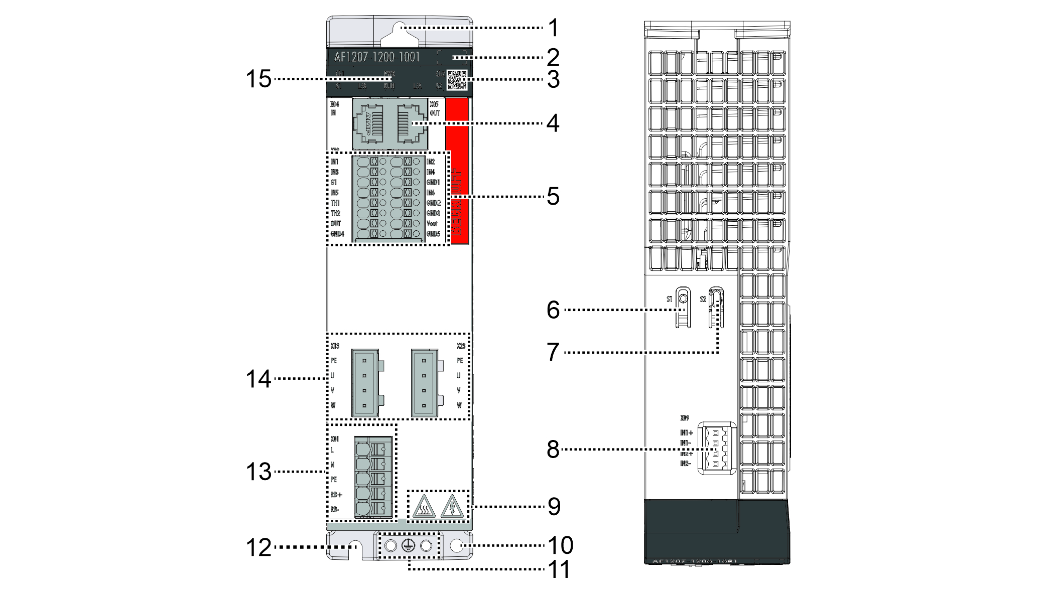
Product overview
 | The areas, functions and slots shown in the figure may vary depending on the module version and are provided here for clarity. |
|
Position |
Name |
Explanation |
|---|---|---|
1 | Mounting hole | For mounting the variable frequency drive in the control cabinet |
2 | Position field | for equipment identification |
3 | DataMatrix code | contains BTN for identification, for further information see name plate |
4 | EtherCAT slot | For connecting the EtherCAT connector to IN X4/OUT X5 |
5 | I/O connection | For connecting the I/O signals to X02 and Use of internal field voltage 24 V |
6 | Push button S1 | for internal purposes |
7 | Push button S2 | TwinSAFE actuation button |
8 | TwinSAFE I/O slot | For connecting the TwinSAFE plug to X09 |
9 | Safety pictograms | for further information, see For your safety |
10 | Mounting hole | For mounting the optional footprint filter to the economy variable frequency drive |
11 | Grounding | Grounding symbol and double connection point with pre-assembled grounding screws for connecting the protective conductor |
12 | Mounting hole | For mounting the variable frequency drive in the control cabinet |
13 | Network connection | For connecting the mains supply to X01 |
14 | Motor slot | For connecting the motor connector to X13/X23 |
15 | Display | Display for function and status display, see Display |