Settings in the CoE register
(Master TwinCAT 2.11 R3)
The data provided in this section as an example refer to an AM3121-0200-0001 servomotor from Beckhoff Automation. For other motors the values may vary, depending on the application.
Table of contents |
|---|
Inserting the motor XML file
 | Downloading the EL72x1 motor XML files The motor XML files are available for download from the Beckhoff website. |
To facilitate commissioning of the EL72x1 servo terminal, motor XML files are provided for the servomotors that are supported by the EL72x1. The XML files can be read in the System Manager. All CoE parameters and DS402 parameters are then set as required.
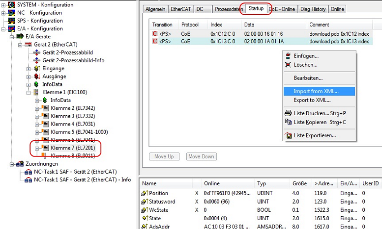
- To read the motor XML file select the EL72x1 and open the Startup tab. Right-click in the empty field and select Import from XML... (see Fig. Importing the motor XML file).
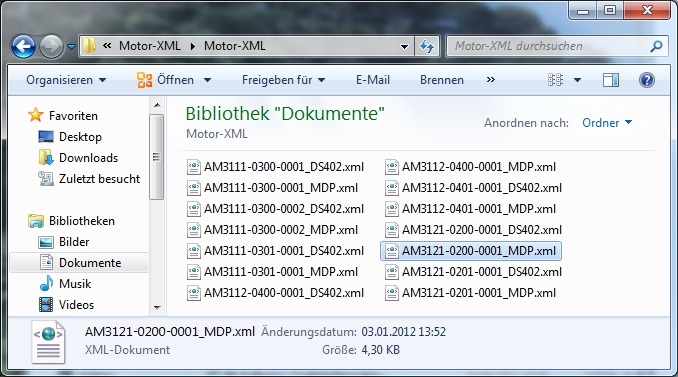
- Select the motor XML file that matches the connected motor (see Fig. Selecting the correct motor XML file)
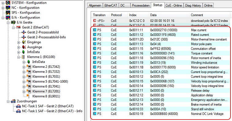
- All required parameters are then set, and the motor can be put into operation (see Fig. CoE parameters of the motor XML file).
| Startup list Any further application-specific settings should also be implemented in the Startup list. Otherwise the modified settings will be overwritten next time the terminal starts up. |
Adaptation of current and voltage
Notice | |
The motor may overheat! In order to prevent overheating of the connected motor, it is important to adjust the voltage of the servo terminal to the actually connected voltage. |
To this end set the index 0x8010:19 "Nominal DC Link Voltage" of the connected voltage as required
Setting further parameters
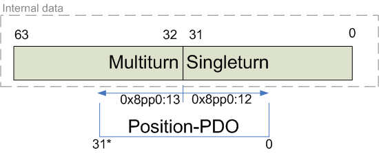
Single-turn Bits (MDP742: Index 0x8000:12 / DS402: Index 0x2010:12) / Multi-turn Bits (MDP742: Index 0x8000:13 / DS402: Index 0x2010:13)
Here the user can specify how many single-turn and multi-turn bits the terminal should display. A total of 32 bits are available. These 32 bits can be subdivided as required.
The standard setting is 20 single-turn bits and 12 multi-turn bits.
Singleturn bits: number of bits relating to the resolution of one rotor rotation.
Multiturn bits: after a rotor rotation the multi-turn bits are incremented by one.
Notice | |
The motor may overheat! If the number of single-turn bits is changed, the scaling factor in the NC has to be adjusted |
Automatic gain control
Each resolver has a small difference between the amplitude of the sine and cosine tracks (see Fig. Resolver gain adjustment). This deviation depends on the variance of the components and other factors and may vary from motor to motor.
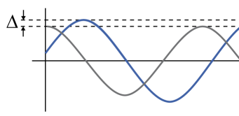
The EL72x1 automatically corrects this small difference in the resolver amplitudes, if the function "Automatic gain control" is active. The correction takes some time, approx. 100 revolutions. The means that the precision during this time is slightly lower than after the correction.
To avoid this small initial inaccuracy, during the commissioning phase, after approx. 100 revolutions, the user can read the "Automatic resolver gain value" determined by the terminal (MDP742: 0x9008:12 / DS402: Index 0x2058:12) and transfer it to "Resolver gain adjustment" (MDP742: Index 0x8008:12 / DS402: Index 0x2018:12). The value entered there is the starting point for the correction. Please note that the value varies from motor to motor. If the motor is replaced, the process must be repeated.
The function "Automatic gain control" can activated or deactivated with "Enable automatic gain control" (MDP742: Index 0x8008:02 / DS402: Index 0x2018:02).
Torque limitation (MDP742: Index 0x7010:0B / DS402: Index 0x6072:0)
Limits the current / torque to this value. The value is specified in 1000th of the rated current.
Integral velocity controller component Tn (MDP742: Index 0x8010:14 / DS402: Index 0x2002:14)
The values specified here are exemplary, although in most cases they have led to excellent results. Depending on the application, other values may yield better results.
- Reduce the value, until the motor starts to oscillate slightly. Then increase the value by 10%.
Proportional velocity controller component Kp (MDP742: Index 0x8010:15 / DS402: Index 0x2002:15)
The values specified here are exemplary, although in most cases they have led to excellent results. Depending on the application, other values may yield better results.
- Increase the value, until the motor starts to oscillate slightly. Then reduce the value by 80%.