Operating modes and settings
Presentation, index 0x80x0:02
The measured value output is set in factory to two's complement representation (signed integer).
Index 0x80x0:02 offers the possibility to change the method of representation of the measured value.
- Signed integer:
The measured value is presented in two’s complement format.
Maximum display range EL3602:
Measuring range | Measuring range | Measuring range | Measuring range | Output value |
|---|---|---|---|---|
+ 10 V | + 5 V | + 2.5 V | + 1.25 V | 7F FF FF FF |
+ 5 V | + 2.5 V | + 1.25 V | + 0.625 V | 3F FF FF FF |
0 V | 0 V | 0 V | 0 V | 00 00 00 00 |
- 5 V | - 2.5 V | - 1.25 V | - 0.625 V | C0 00 00 00 |
- 10 V | - 5 V | - 2.5 V | - 1.25 V | 80 00 00 01 |
Maximum display range EL3602-0010:
Measuring range | Output value |
|---|---|
+ 0.075 V | 7F FF FF FF |
+ 0.0375 V | 3F FF FF FF |
0 V | 00 00 00 00 |
- 0.0375 V | C0 00 00 00 |
- 0.075 V | 80 00 00 01 |
Maximum display range EL3602-0002:
Measuring range | Output value |
|---|---|
+ 200 mV | 7F FF FF FF |
+ 100 mV | 3F FF FF FF |
0 V | 00 00 00 00 |
- 200 mV | C0 00 00 00 |
- 100 mV | 80 00 00 01 |
Maximum display range EL3612:
Measuring range | Output value |
|---|---|
20 mA | 7F FF FF FF |
10 mA | 3F FF FF FF |
0 mA | 00 00 00 00 |
Maximum display range EL3621-0020:
Measuring range | Output value |
|---|---|
20 mA | 7F FF FF FF |
12 mA | 3F FF FF FF |
4 mA | 00 00 00 00 |
- Absolute value with MSB as sign:
The measured value is output in magnitude-sign format.
Maximum display range EL3602:
Measuring range | Measuring range | Measuring range | Measuring range | Output value |
|---|---|---|---|---|
+ 10 V | + 5 V | + 2.5 V | + 1.25 V | 7F FF FF 00 |
+ 5 V | + 2.5 V | + 1.25 V | + 0.625 V | 3F FF FF 00 |
+ 0 V | + 0 V | + 0 V | + 0 V | 00 00 00 00 |
- 0 V | - 0 V | - 0 V | - 0 V | 80 00 00 00 |
- 5 V | - 2.5 V | - 1.25 V | - 0.625 V | C0 00 00 00 |
- 10 V | - 5 V | - 2.5 V | - 1.25 V | FF FF FF FF |
Maximum display range EL3602-0010:
Measuring range | Output value |
|---|---|
+ 0.075 V | 7F FF FF 00 |
+ 0.0375 V | 3F FF FF 00 |
+ 0 V | 00 00 00 00 |
- 0 V | 80 00 00 00 |
- 0.0375 V | C0 00 00 00 |
- 0.075 V | FF FF FF FF |
Maximum display range EL3602-0002:
Measuring range | Output value |
|---|---|
+ 200 mV | 7F FF FF 00 |
+ 100 mV | 3F FF FF 00 |
+0 V | 00 00 00 00 |
-0 V | 80 00 00 00 |
- 200 mV | C0 00 00 00 |
- 100 mV | FF FF FF FF |
Maximum display range EL3612:
Measuring range | Output value |
|---|---|
20 mA | 7F FF FF 00 |
10 mA | 3F FF FF 00 |
0 mA | 00 00 00 00 |
Maximum display range EL3621-0020:
Measuring range | Output value |
|---|---|
20 mA | 7F FF FF 00 |
12 mA | 3F FF FF 00 |
4 mA | 00 00 00 00 |
- Right adjust 24 bits:
The measured value is output with a resolution of 24 bit.
Maximum display range EL3602:
Measuring range | Measuring range | Measuring range | Measuring range | Output value |
|---|---|---|---|---|
+ 10 V | + 5 V | + 2.5 V | + 1.25 V | 00 7F FF FF |
+ 5 V | + 2.5 V | + 1.25 V | + 0.625 V | 00 3F FF FF |
0 V | 0 V | 0 V | 0 V | 00 00 00 00 |
- 5 V | - 2.5 V | - 1.25 V | - 0.625 V | FF C0 00 00 |
- 10 V | - 5 V | - 2.5 V | - 1.25 V | FF 80 00 00 |
Maximum display range EL3602-0010:
Measuring range | Output value |
|---|---|
+ 0.075 V | 00 7F FF FF |
+ 0.0375 V | 00 3F FF FF |
0 V | 00 00 00 00 |
- 0.0375 V | FF C0 00 00 |
- 0.075 V | FF 80 00 00 |
Maximum display range EL3602-0002:
Measuring range | Output value |
|---|---|
+ 200 mV | 00 7F FF FF |
+ 100 mV | 00 3F FF FF |
0 V | 00 00 00 00 |
- 200 mV | FF C0 00 00 |
- 100 mV | FF 80 00 00 |
Maximum display range EL3612:
Measuring range | Output value |
|---|---|
20 mA | 00 7F FF FF |
10 mA | 00 3F FF FF |
0 mA | 00 00 00 00 |
Maximum display range EL3621-0020:
Measuring range | Output value |
|---|---|
20 mA | 00 7F FF FF |
12 mA | 00 3F FF FF |
4 mA | 00 00 00 00 |
Siemens Bits, Index 0x80x0:05
If this bit is set, status displays are superimposed on the lowest three bits. In the error case "overrange" or "underrange", bit 0 is set.
Undershoot and overshoot of the measuring range (under-range, over-range), index 0x6000:01, 0x6000:02
Undershoot:
Index 0x60x0:01 and index 0x60x0:07 (underrange and error bit) are set. The linearization of the characteristic curve is continued with the coefficients of the under-range limit up to the limit stop of the A/D converter or to the minimum value of 0x80 00 00 01.
Overshoot:
Index 0x60x0:02 and index 0x60x0:07 (overrange and error bit) are set. The linearization of the characteristic curve is continued with the coefficients of the over-range limit up to the limit stop of the A/D converter or to the maximum value of 0x7F FF FF FF .
For overrange or underrange the red error LED is switched on. Observe the note below regarding this
 | Error bit (index 0x60x0:07) and Error LED The Error bit and the Error LED are not synonymous! |
Notch filter, conversion times, index 0x80x0:06
The EL36xx terminals are equipped with two filters:
- firstly an analog low-pass filter (see Technical Data)
- then a digital adjustable filter: The SigmaDelta converter samples the input voltage at a rate > 1 MHz and then filters according to the filter setting specified in CoE index 0x8000:15.
The filter performs a notch filter function and determines the conversion time of the channel or terminal. The higher the filter frequency, the faster the conversion time. The conversion time can be influenced towards longer conversion times by a CoE setting that deviates from the default state, such as Enable User Scale. The EL36xx Terminals have no FastMode.
| Index 0x80x0:06 The filter function is always active even if the bit is not set, since this is obligatory for the measurement process! |
| The filter characteristics are set via index 0x8000:15 The filter frequencies are set for all channels of the EL36xx terminals centrally via index 0x8000:15 (channel 1). |
Typical conversion times EL36xx
|
|
Conversion time (update time) | |
|---|---|---|
|
Filter frequency |
1 channel operation |
2 channel operation |
|
5 Hz |
200 ms |
400 ms |
|
10 Hz |
100 ms |
200 ms |
|
50 Hz |
20.5 ms |
41 ms |
|
60 Hz |
17 ms |
34 ms |
|
100 Hz |
10.5 ms |
21 ms |
|
500 Hz |
3 ms |
6 ms |
|
1000 Hz |
1.8 ms |
4 ms |
|
2000 Hz |
1.3 ms |
3 ms |
|
3750 Hz |
1 ms |
3 ms |
|
7500 Hz |
1 ms |
3 ms |
|
15000 Hz |
1 ms |
3 ms |
|
30000 Hz |
1 ms |
3 ms |
Table 2: Conversion times in relation to the filter frequencies (subject to change!)
1/2 channel operation
The EL36xx can be changed to single-channel mode via the process data selection. The EL36xx operates by default in 2-channel mode.
To do this, the activation checkmark in front of 0x1A01 in the SyncManager 3 (SM3, "Inputs") must be removed; following an EtherCAT/TwinCAT restart only one channel is then active.
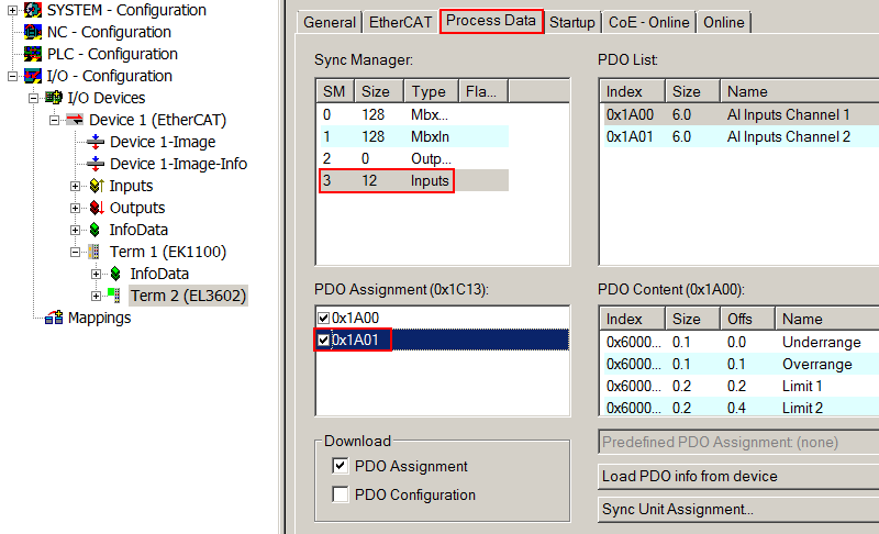 Fig.142: Selection of process data
Limit 1 and Limit 2, Index 0x80x0:13, Index 0x80x0:14
If the value exceeds or falls below these values, which can be entered in the indices 0x80x0:13 and 0x80x0:14, then the bits in the indices 0x60x0:03 and 0x60x0:05 are set accordingly (see example below). The indices 0x80x0:07 or 0x80x0:08 serve to activate the limit value monitoring.
Example for EL3602:
Channel 1; Limit 1 and Limit 2 enabled
Limit 1 = 2.8 V
Limit 2 = 7.4 V
Measuring range: +/- 10
Presentation: signed integer
Entry in index (Limit 1): 0x8000:13
(2.8 V / 10 V) x 232 / 2 - 1 = 601,295,421dec
Entry in index (Limit 2): 0x8000:14
(7.4 V / 10 V) x 232/2 - 1 = 1,589,137,899dec
Output:
Input channel 1: 1.8 V:
Index 0x60x0:03: 0x02hex, (Limit 1, limit value undershot),
Index 0x60x0:05: 0x02hex, (Limit 2, limit value undershot),
Input channel 1: 4.2 V:
Index 0x60x0:03: 0x01hex, (Limit 1, limit value exceeded),
Index 0x60x0:05: 0x02hex, (Limit 2, limit value undershot)
Input channel 1: 8.5 V:
Index 0x60x0:03: 0x01hex, (Limit 1, limit value exceeded),
Index 0x60x0:05: 0x01hex, (Limit 2, limit value exceeded)
User scaling, index 0x80x0:01
The user scaling is enabled via index 0x80x0:01. Parameterization takes place via the indices
|
• |
0x80x0:11 |
|
• |
0x80x0:12 |
Vendor calibration, index 0x80x0:0B
The vendor calibration is enabled via index 0x80x0:0B. Parameterization takes place via the indices
|
• |
0x80xF:01 |
|
• |
0x80xF:02 |
|
• |
0x80xF:03 |
|
• |
0x80xF:04 |
|
• |
0x80xF:05 |
|
• |
0x80xF:06 |
|
• |
0x80xF:07 |
|
• |
0x80xF:08 |
|
• |
0x80xF:09 |
| Vendor calibration The vendor reserves the authority for the basic calibration of the terminals. Therefore, the vendor calibration cannot be changed. |
User calibration, index 0x80x0:17, 0x80x0:18
The user calibration is enabled via index 0x80x0:0A. Parameterization takes place via the indices
|
• |
0x80x0:17 |
|
• |
0x80x0:18 |
Process data calculation
The terminal records measured values continuously and places the raw values of its A/D converter into the ADC raw value object 0x80xE:011 or 0x80xE:02. The calculation of the correction with the vendor calibration values takes place after each acquisition of the analog signal. User scaling then follows (optionally):
|
YH = (XADC - BK) x AK |
Measured value following manufacturer calibration (corresponds to YA if index 0x80x0:0A is inactive) |
|
YA = YH x AW x 22 -16+ BW |
Measured value following user scaling |
|
Name |
Name |
Index (hex) |
|---|---|---|
|
XADC |
Output value of the A/D converter | |
|
BK |
Manufacturer calibration offset (only changeable if the object Producer codewordF008 is set) | |
|
AK |
Manufacturer calibration gain (only changeable if the object Producer codewordF008 is set) | |
|
BW |
User scaling offset (can be activated via index 0x80x0:0A) | |
|
AW |
User scaling gain (can be activated via index 0x80x0:0A) | |
|
YA |
Process data for controller |
- |
Measuring range (Range), Index 0x80x0:19 (EL3602 only)
The EL3602 can display four measuring ranges, which can be set via Index 0x80x0:19 (+/- 1.25 V; +/- 2.5 V; +/- 5 V; +/- 10 V)
Producer Codeword
| Producer Codeword The vendor reserves the authority for the basic calibration of the terminals. The Producer codeword is therefore at present reserved. |