MP_EPIV_V4_Configuration
This function block is used to configure the 2-way EPIV V4 DN 15..50 EP..R2+(K)BAC. For more information please visit www.belimo.com.
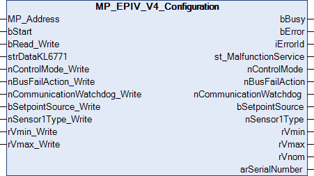
MP_Address is used to specify the MP-Bus device with which the function block is to communicate. bStart activates communication with the MP-Bus device. bBusy indicates that the function block is active. bError is used to indicate an error in communication with the actuator. The type of the error can be read with iErrorId.
 Inputs
VAR_INPUT
  MP_Address                   : USINT := 1;
  bStart                       : BOOL;
  bRead_Write                  : BOOL;
  strDataKL6771                : DataKL6771;
  nControlMode_Write           : E_MP_EV_V4_ControlMode := 1;
  nBusFailAction_Write         : E_MP_EV_V4_BusFailAction;
  nCommunicationWatchdog_Write : UINT := 120;
  bSetpointSource_Write        : BOOL := TRUE;
  nSensor1Type_Write           : E_MP_EV_V4_Sensor1Type;
  rVmin_Write                  : LREAL;
  rVmax_Write                  : LREAL := 100;
END_VAR
Name | Type | Description |
|---|---|---|
MP_Address | USINT | MP-Bus address of the slave. |
bStart | BOOL | A positive edge starts the function block. If this remains continuously TRUE, the function block will be activated cyclically with a period specified by the time in TMPolling. |
bRead_Write | BOOL | If FALSE then READ only; if TRUE then READ and WRITE. |
strDataKL6771 | The data structure with which the KL6771() function block must be linked. | |
nControlMode_Write | Control mode | |
nBusFailAction_Write | Bus failure action | |
nCommunicationWatchdog_Write | UINT | Communication monitoring in s (0..3600). |
bSetpointSource_Write | BOOL | TRUE = bus; FALSE = analog. |
nSensor1Type_Write | Sensor 1 type | |
rVmin_Write | LREAL | Min. setpoint in % (0...Vmax). Vmin must be smaller than Vmax. |
rVmax_Write | LREAL | Max. setpoint in % (25...100). Standard 100 %. Refers to Vnom and is taken into account when control mode = flow control. |
 Outputs
VAR_OUTPUT
  bBusy                  : BOOL;
  bError                 : BOOL;
  iErrorId               : MP_Error;
  st_MalfunctionService  : St_MP_EV_V4_MalfunctionServiceInfo;
  nControlMode           : E_MP_EV_V4_ControlMode;
  nBusFailAction         : E_MP_EV_V4_BusFailAction;
  nCommunicationWatchdog : UINT;
  bSetpointSource        : BOOL;
  nSensor1Type           : E_MP_EV_V4_Sensor1Type;
  rVmin                  : LREAL;
  rVmax                  : LREAL;
  rVnom                  : LREAL;
  arSerialNumber         : ARRAY[0..1] OF DWORD;
END_VAR
Name | Type | Description |
|---|---|---|
bBusy | BOOL | This bit is set for as long as the function block is active. |
bError | BOOL | This output goes TRUE as soon as an error occurs. This error is described via the iErrorId variable. |
iErrorId | This output outputs an error code in the event of an error. bError goes TRUE at the same time. | |
st_MalfunctionService | Malfunction and service information | |
nControlMode | Control mode | |
nBusFailAction | Bus failure action | |
nCommunicationWatchdog | UINT | Communication monitoring in sec (0...3600). Not functional (reserved for future extensions). |
bSetpointSource | BOOL | TRUE = bus; FALSE = analog |
nSensor1Type | Sensor 1 Type | |
rVmin
| LREAL | Min. setpoint in % (0...Vmax). Refers to Vnom and is taken into account when control mode = flow control. |
rVmax | LREAL | Max. setpoint in % (25...100). Refers to Vnom and is taken into account when control mode = flow control. |
rVnom | LREAL | Nominal volume flow in l/s (0...100) |
arSerialNumber | ARRAY OF DWORD | Serial number of the device. |
Requirements
Development environment | PLC library to include |
|---|---|
TwinCAT from v3.1.4024.46 | Tc2_MPBus from 3.6.1.0 |