Control commands of an axis
|
Feed Enable, Axis | |
|
Description |
Axis-specific Feed Enable The Feed Enable must be set for all axes to be moved. If this is not the case, no path movement occurs. |
|
|
MCControlBoolUnit, see description Control Unit |
|
Characteristics |
SERCOS drives In the case of SERCOS drives, the data item is derived from bit 13 of the control word. |
|
Access |
PLC reads Request + State and writes Command + Enable |
|
ST path |
pAC[axis_idx]^.addr^.McControlLr_Data.MCControlBoolUnit_ReleaseFeedhold |
|
Commanded, requested, and return value | |
|
ST element |
. X_Command .X_Request |
|
Data type |
BOOL |
|
Value range |
[TRUE = Drive Enable, Transition TRUE -> FALSE: The drive is shut down in compliance with the acceleration parameters. FALSE = Drive HALT] |
|
Return value | |
|
ST element |
. X_State |
|
Data type |
BOOL |
|
Value range |
[TRUE = Drive Enable, FALSE = Drive HALT] |
|
Redirection | |
|
ST element |
. X_Enable |
 Data type
|
Feed Hold ON/OFF, axis | |
|
Description |
Axis-specific Feed Hold The axis-specific Feed Hold acts on an axis if this axis is currently not being traversed in the path network but in Manual mode or as an independent axis. Otherwise, the global Feed Hold of the channel acts for it. |
|
|
MCControlBoolUnit, see description Control Unit |
|
Access |
PLC reads Request + State and writes Command + Enable |
|
ST path |
pAC[axis_idx]^.addr^.McControlIpo_Data. MCControlBoolUnit_Feedhold |
|
Commanded, requested and return value | |
|
ST element |
.X_Command .X_Request .X_State |
|
Data type |
BOOL |
|
Value range |
[TRUE = Feed Hold on, FALSE = Feed Hold off] |
|
Redirection | |
|
ST element |
. X_Enable |
|
Feed Override, axis | |
|
Description |
Axis-specific feed override The axis-specific feed override allows to weight the axis velocity with an additional percentage factor. The axis-specific feed override acts on an axis if this axis is currently not being traversed in the path network but in Manual mode or as an independent axis. Otherwise, the global override of the channel acts for it. |
|
|
MCControlUNS16Unit, see description Control Unit |
|
Access |
PLC reads Request + State and writes Command + Enable |
|
ST path |
pAC[axis_idx]^.addr^.McControlIpo_Data.MCControlUNS16Unit_Override |
|
Commanded, requested, and return value | |
|
ST element |
.D_Command .D_Request .D_State |
|
Unit |
0.1 % |
|
Data type |
UINT |
|
Value range |
[0, P-AXIS-00109] P-AXIS-00109 is an axis-specific parameter. The default value is 1000. See [Axis Parameter]. |
|
Redirection | |
|
ST element |
. X_Enable |
|
Feed override valid, axis | |
|
Description |
Axis-specific Feed Override valid |
|
|
MCControlBoolUnit, see description Control Unit |
|
Access |
PLC reads Request + State and writes Command + Enable |
|
ST path |
pAC[axis_idx]^.addr^.McControlIpo_Data.MCControlBoolUnit_OverrideValid |
|
Commanded, requested and return value | |
|
ST element |
.X_Command .X_Request .X_State |
|
Data type |
BOOL |
|
Value range |
[TRUE = Axis-specific Feed Override valid, FALSE] |
|
Redirection | |
|
ST element |
. X_Enable |
|
Drive ON | |
|
Description |
Drive ON |
|
|
MCControlBoolUnit, see description Control Unit |
|
Characteristics |
SERCOS drives In the case of SERCOS drives, the data item is derived from bit 15 of the control word. |
|
Access |
PLC reads Request + State and writes Command + Enable |
|
ST path |
pAC[axis_idx]^.addr^.McControlLr_Data.MCControlBoolUnit_DriveOn |
|
Commanded and requested value | |
|
ST element |
.X_Command .X_Request |
|
Data type |
BOOL |
|
Value range |
[TRUE = Drive ON, Transition TRUE -> FALSE: The drive is shut down as best possible. FALSE = Drive OFF] |
|
Return value | |
|
ST element |
. X_State |
|
Data type |
BOOL |
|
Value range |
[TRUE = Drive ON, FALSE = Drive OFF] |
|
Redirection | |
|
ST element |
. X_Enable |
|
Controller Enable | |
|
Description |
Controller Enable “axis-specific” torque connection. |
|
|
MCControlBoolUnit, see description Control Unit |
|
Characteristics |
SERCOS drives In the case of SERCOS drives, the data item is derived from bit 14 of the control word. |
|
Access |
PLC reads Request + State and writes Command + Enable |
|
ST path |
pAC[axis_idx]^.addr^.McControlLr_Data.MCControlBoolUnit_TorquePermission |
|
Commanded, requested, and return value | |
|
ST element |
.X_Command .X_Request .X_State |
|
Data type |
BOOL |
|
Value range |
[TRUE = Torque connection, FALSE = Drive is idle] |
|
Redirection | |
|
ST element |
. X_Enable |
The following diagram shows the combination of control units of the HLI and the SERCOS-Controlword respectively SERCOS-Statusword.
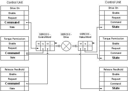 Fig.8: Figure 2-1: Combination control units and SERCOS Control- respectively Statusword
|
Reference cam | |
|
Description |
Signal of a reference cam when homing. |
|
|
MCControlBoolUnit, see description Control Unit |
|
Characteristics |
Commanding this signal acts only if the characteristic parameter lr_hw[i].cam_direct_access = 0 is set in the axis machine data record of the relevant axis. Using characteristic parameter lr_hw[i].cam_level in the axis machine data record can program the action of this command from high-active to low-active. The action in the default case is described below. |
|
Access |
PLC reads Request + State and writes Command + Enable |
|
ST path |
pAC[axis_idx]^.addr^.McControlLr_Data.MCControlBoolUnit_ReferenceCam |
|
Commanded, requested, and return value | |
|
ST element |
.X_Command .X_Request .X_State |
|
Data type |
BOOL |
|
Value range |
[TRUE = Reference cam switched, FALSE = Reference cam not switched] |
|
Redirection | |
|
ST element |
. X_Enable |
|
Reduced feed, axis | |
|
Description |
If this signal is activated axis velocity is reduced, in case G00 or G01 is commanded, to the values defined in P-AXIS-00214 respectively P-AXIS-00155. See also [Axis Parameter]. |
|
|
MCControlBoolUnit, see description Control Unit |
|
Characteristics |
Is the axis member of a channel (axes group), the limitations of the other axes that are part of the motion are considered. The path feed that takes effect in such a case is evaluated that no axis that is part of the actual motion exceeds their configured feed limit. In this case the behavior is identical to the command via the channel specific control unit. |
|
Access |
PLC reads Request + State and writes Command + Enable |
|
ST path |
pAC[axis_idx]^.addr^.McControlIpo_Data.MCControlBoolUnit_ReducedFeed |
|
Commanded, requested, and return value | |
|
ST element |
X_Command .X_Request .X_State |
|
Data type |
BOOL |
|
Value range |
[TRUE = Reduced feed active, FALSE = Reduced feed not active] |
|
Redirection | |
|
ST element |
. X_Enable |
|
Reduced feed in zone 1, axis | |
|
Description |
When this signal is activated and axis position is within the values defined in P-AXIS-00085 and P-AXIS-00093 axis velocity is reduced to the value defined in P-AXIS-00030. If necessary velocity is reduced after entering the zone. See also [Axis Parameter]. |
|
|
MCControlBoolUnit, see description Control Unit |
|
Characteristics |
Is the axis member of a channel (axes group), the limitations of the other axes that are part of the motion and located within their configured zone, are considered. |
|
Access |
PLC reads Request + State and writes Command + Enable |
|
ST path |
pAC[axis_idx]^.addr^.McControlIpo_Data.MCControlBoolUnit_ReducedFeedZone |
|
Commanded, requested, and return value | |
|
ST element |
X_Command .X_Request .X_State |
|
Data type |
BOOL |
|
Value range |
[TRUE = Reduced feed in zone 1 active, FALSE = Reduced feed in zone 1 not active] |
|
Redirection | |
|
ST element |
. X_Enable |
|
Reduced feed in zone 2, axis | |
|
Description |
When this signal is activated and axis position is within the values defined in P-AXIS-00097 and P-AXIS-00105 path velocity is reduced to the value defined in P-AXIS-00030. If necessary velocity is reduced after entering the zone. |
|
|
MCControlBoolUnit, see description Control Unit |
|
Characteristics |
Is the axis member of a channel (axes group), the limitations of the other axes that are part of the motion and located within their configured zone, are considered. |
|
Access |
PLC reads Request + State and writes Command + Enable |
|
ST path |
pAC[axis_idx]^.addr^.McControlIpo_Data.MCControlBoolUnit_ReducedFeedZone2 |
|
Commanded, requested, and return value | |
|
ST element |
X_Command .X_Request .X_State |
|
Data type |
BOOL |
|
Value range |
[TRUE = Reduced feed in zone 2 active, FALSE = Reduced feed in zone 2 not active] |
|
Redirection | |
|
ST element |
. X_Enable |
|
Suppression of Read-In Enable | |
|
Description |
Suppression of Read-In Enable If the Read-In Enable is cancelled (setting NoEfg), the interpolator does not read any new advance-decoded NC forward-traverse information, i.e. the movement is stopped after the end of the current jobs in the interpolator. |
|
|
MCControlBoolUnit, see description Control Unit |
|
Access |
PLC reads Request + State and writes Command + Enable |
|
ST path |
pAC[axis_idx]^.addr^.McControlIpo_Data.MCControlBoolUnit_NoEfg |
|
Commanded, requested, and return value | |
|
ST element |
.X_Command .X_Request .X_State |
|
Data type |
BOOL |
|
Value range |
[TRUE = No Read-In Enable, FALSE = Read-In Enable] |
|
Redirection | |
|
ST element |
. X_Enable |
|
Machining Simulation, Axis | |
|
Description |
Activates and deactivates axis-specific machining simulation. During machining simulation, all axis-specific technology commands of the NC program are no longer output to the PLC but are acknowledged internally. |
|
|
MCControlBoolUnit, see description Control Unit |
|
Access |
PLC reads Request + State and writes Command + Enable |
|
ST path |
pAC[axis_idx]^.addr^.McControlIpo_Data.MCControlBoolUnit_MachiningSimu |
|
Commanded, requested, and return value | |
|
ST element |
.X_Command .X_Request .X_State |
|
Data type |
BOOL |
|
Value range |
[TRUE = No Read-In Enable, FALSE = Read-In Enable] |
|
Redirection | |
|
ST element |
. X_Enable |
|
Tracking Operation | |
|
Description |
The axis is set to tracking operation (follow up), i.e. the control loop is opened. The command position implicitly is set to the actual position. |
|
|
MCControlBoolUnit, see description Control Unit |
|
Characteristics |
Because the command value takes over the position lag of the actual position, it is possible that any external force (e.g. weight of axis) slowly moves the axis (drift). |
|
Access |
PLC reads Request + State and writes Command + Enable |
|
ST-path |
pAC[axis_idx]^.addr^.McControlLr_Data.MCControlBoolUnit_FollowUp |
|
Commanded, requested, and return values | |
|
ST element |
.X_Command .X_Request .X_State |
|
Data type |
BOOL |
|
Range |
[TRUE = control loop open, FALSE] |
|
Redirection | |
|
ST element |
. X_Enable |
|
Ignore minimal tool velocity | |
|
Description |
If a value for minimal tool velocity is configured for a tool, NC-Kernel by default takes care, that this limit is not underrunned by commanding an override. This control unit is used to avoid this behavior of the NC-Kernel and the override takes effect onto the axis as commanded. |
|
|
MCControlBoolUnit, see description Control Unit |
|
Characteristics |
Control unit only takes effect if the axis is a spindle. |
|
Access |
PLC reads Request + State and writes Command + Enable |
|
ST-path |
pAC[axis_idx]^.addr^.McControlIpo_Data.MCControlBoolUnit_IgnoreVbMinTool |
|
Commanded, requested, and return values | |
|
ST element |
.X_Command .X_Request .X_State |
|
Data type |
BOOL |
|
Range |
[TRUE = Ignore minimal tool velocity in case of override command, FALSE] |
|
Redirection | |
|
ST element |
. X_Enable |
|
Driving out gantry difference | |
|
Description |
If the axis is a gantry slave axis and master and slave are referenced the position difference between master and slave axis is driven out. |
|
|
MCControlBoolUnit, see description Control Unit |
|
Characteristics |
|
|
Access |
PLC reads Request + State and writes Command + Enable |
|
ST-path |
pAC[axis_idx]^.addr^.McControlLr_Data.MCControlBoolUnit_GantryOn |
|
Commanded, requested, and return values | |
|
ST element |
.X_Command .X_Request .X_State |
|
Data type |
BOOL |
|
Range |
[TRUE = driving out gantry difference allowed, FALSE] |
|
Redirection | |
|
ST element |
. X_Enable |
|
Overtake reference position | ||
|
Description |
Overtake reference position and mark axis as referenced on a rising edge of this control unit. Depending on the value of P-AXIS-00278 the axis position is set to the following values: | |
|
P-AXIS-00278 |
Reference position of the axis | |
|
ABSOLUT |
Value of P-AXIS-00152 | |
|
OFFSET |
Encoder position of the drive + P-AXIS-00279 | |
|
PLC |
Value of control unit MCControlSGN32Unit | |
|
PLC_OFFSET |
Encoderposition of the drive + Value of control unit refpos_position. | |
|
The variable X_State shows if the reference position was set manually and as a result the coordinate system has been shifted. The manual setting can be removed by a CNC-controlled homing (G74). Also, for an axis with absolute measurement system the reference position can be set manually. | ||
|
|
MCControlBoolUnit, see description Control Unit | |
|
Characteristics |
Edge detection. Functionality is active on rising edge on X_Command. | |
|
Access |
PLC reads Request + State and writes Command + Enable | |
|
ST-path |
pAC[axis_idx]^.addr^.McControlLr_Data. MCControlBoolUnit_SetReferencePosition | |
|
Commanded, requested, and return values | ||
|
ST element |
.X_Command .X_Request .X_State | |
|
Data type |
BOOL | |
|
Range |
[TRUE, FALSE] | |
|
Redirection | ||
|
ST element |
. X_Enable | |
|
Reference position to overtake | ||
|
Description |
If in the axis parameter list the value of P-AXIS-00278 is set to „PLC”‚ or to „PLC_OFFSET” the value of this control unit is used as reference position if the control unit MCControlSGN32_RefposPosition is used to trigger overtaking of the reference position. | |
|
P-AXIS-00278 |
Reference position of the axis | |
|
PLC |
Value of this control unit. | |
|
PLC_OFFSET |
Encoder position of the drive + Value of this control unit. | |
|
|
MCControlSGN32Unit, see description Control Unit | |
|
Characteristics |
| |
|
Access |
PLC reads Request + State and writes Command + Enable | |
|
ST-path |
pAC[axis_idx]^.addr^.McControlLr_Data. MCControlSGN32UNIT | |
|
Commanded, requested, and return values | ||
|
ST element |
.D_Command .D_Request .D_State | |
|
Data type |
DINT | |
|
Dimension |
0.1 um resp.10-4° | |
|
Range |
[MIN_DINT, MAX_DINT] | |
|
Redirection | ||
|
ST element |
. X_Enable | |
|
Clear of homing state | |
|
Description |
If axis has been homed by set of reference position of by G74, this state can be cleared again by usage of the actual control unit. If axis has an absolute measurement system, the axis also is considered as „not homed“ afterwards (it can by homed again by standard G74). E.g. by clearing the homing state the checking of software limit switches can by suppressed temporarily. Any position offset activated by „set reference position“ is not cleared by the actual control unit. The variable X_State displays if the axis is „not homed“ (inverse of homed). |
|
|
MCControlBoolUnit, see description Control Unit |
|
Characteristics |
Functionality is commanded by a rising edge at X_Command. |
|
Access |
PLC reads Request + State and writes Command + Enable |
|
ST-path |
pAC[axis_idx]^.addr^.McControlLr_Data.MCControlBoolUnit_ClearReferencePosition |
|
Commanded, requested, and return values | |
|
ST element |
.X_Command .X_Request . X_State |
|
Data type |
BOOL |
|
Ramge |
[TRUE, FALSE] |
|
Redirection | |
|
ST element |
. X_Enable |
|
Definition of axis couplings | |
|
Description |
With this control unit there can be defined axis couplings defined for the axis. It is possible to influence the movement of the axis additionally or exclusively by the movement of another axis. Further details can be taken from the documentation [Axis couplings via HLI]. |
|
|
MCControlAxisCouplingUnit, s. Description Control Unit |
|
Access |
PLC reads State and writes Command + Enable |
|
ST-path |
pAC[axis_idx]^.addr^.McControlLr_Data. |
|
Commanded values | |
|
ST element |
.AxisCouplingCommand |
|
Information flow |
PLC -> CNC |
|
Data type |
|
|
Access |
PLC writes |
|
Return value | |
|
ST element |
.AxisCouplingState |
|
Information flow |
CNC -> PLC |
|
Data type |
|
|
Access |
PLC reads |
|
Redirection | |
|
ST element |
. X_Enable |
|
Axis couplings, state | |
|
Description |
Displays the active axis couplings for this axis. |
|
Information flow |
CNC -> PLC |
|
ST-Path |
pAC[axis_idx]^.addr^.McControlLr_Data. |
|
Data type |
HLIAxisCouplingState |
|
Access |
PLC read |
|
Elements of data type | |
|
Element |
.desc[ ] |
|
Data type |
ARRAY [1 .. HLI_AxisCouplingMax] OF HLIAxisCouplingDesc |
|
Access |
PLC reads |
|
|
|
|
Element |
.X_Active |
|
Data type |
BOOL |
|
Access |
PLC reads |
|
Axis couplings, command | |
|
Description |
In this entry all coupling definitions for an axis is set up. The number of maximal possible coupling definitions is defined in the constant HLI_AxisCouplingMax. See also documentation [Axis couplings via HLI]. |
|
Information flow |
PLC -> CNC |
|
Data type |
HLIAxisCouplingCommand |
|
ST-Path |
pAC[axis_idx]^.addr^.McControlLr_Data. |
|
Access |
PLC write |
|
Elements of data type | |
|
Element |
.desc[ ] |
|
Data type |
ARRAY [1 .. HLI_AxisCouplingMax] OF HLIAxisCouplingDesc |
|
Access |
PLC write |
|
Element |
X_Semaphor |
|
Data type |
BOOL |
|
Access |
Consumption data The CNC overtakes the commanded values it the element is set to TRUE. After proccessing the commanded values, the CNC sets this element back to FALSE. PLC sets element TRUE, if commanded values are ready to be overtaken by CNC. PLC may only change data of desc[..], if the value of the element is TRUE. |
|
Definition of an axis coupling | |
|
Description |
In this entry all coupling definitions for an axis is set up. See also documentation [Axis couplings via HLI]. |
|
Information flow |
PLC -> CNC |
|
Data type |
HLIAxisCouplingDesc |
|
ST-Path |
pAC[axis_idx]^.addr^.McControlLr_Data. pAC[axis_idx]^.addr^.McControlLr_Data. |
|
Access |
Command for axis coupling: PLC writes Status of axis coupling: PLC reads |
|
Elements of data type | |
|
ST element |
.CouplingMode |
|
Data type |
UINT |
|
Value range |
HLI_AXIS_COUPLING_INACTIVE = 0, HLI_AXIS_COUPLING_ZERO = 1, HLI_AXIS_COUPLING_DIRECT = 2, HLI_AXIS_COUPLING_MIRROR = 3 HLI_AXIS_COUPLING_FRACT = 4 |
|
Description |
|
|
|
|
|
ST element |
.AxisNumber |
|
Data type |
UINT |
|
Description |
Logical axis number of source axis. It the axis shall be moved with active coupling by a NC program a coupling command with the logical axis number of the axis itself and coupling mode HLI_AXIS_COUPLING_DIRECT must be defined. |
|
|
|
|
ST element |
.FractNumerator |
|
Data type |
INT |
|
Value range |
The permissible range is [-32768 .... 32767]. A value of zero has the same effect as coupling mode HLI_AXIS_COUPLING_INACTIVE. |
|
Description |
Numerator of coupling factor if coupling mode is set to HLI_AXIS_COUPLING_FRACT. For all other coupling modes this element is not used. The maximal permissible value for the coupling factor desc[idx].FractNumerator / .desc[idx].FractDenominator is HLI_AXIS_COUPLING_FACT_MAX. Exceeding this value leads to error message P-ERR-70397. |
|
|
|
|
ST element |
.FractDenominator |
|
Data type |
INT |
|
Value range |
The permissible range is [-32768 .... 32767], zero excluded. A value of zero in this element leads to error message P-ERR-70396. |
|
Description |
Denominator of coupling factor if coupling mode is set to HLI_AXIS_COUPLING_FRACT. For all other coupling modes this element is not used. The maxima permissible value for the coupling factor desc[idx].FractNumerator / .desc[idx].FractDenominator is HLI_AXIS_COUPLING_FACT_MAX. Exceeding this value leads to error message P-ERR-70397. |
|
Probing signal | |
|
Description |
With this control unit the PLC can provide the probing signal via the HLI. If this control unit is used the axis parameter kenngr.probing_signal_via_plc has to be set to 1. See also [Axis Parameter]. |
|
|
MCControlBoolUnit, see descriptionControl Unit |
|
Characteristics |
Edge detection. The edge set up in axis parameter kenngr.mess_neg_flanke is used to overtake the probing value. |
|
Access |
PLC reads Request + State and writes Command + Enable |
|
ST- Path |
pAC[axis_idx]^.addr^.McControlLr_Data.MCControlBoolUnit_ProbingSignal |
|
Commanded, requested and return values | |
|
ST element |
.X_Command .X_Request . X_State |
|
Data type |
BOOL |
|
Value range |
[TRUE, FALSE] |
|
Redirection | |
|
ST element |
. X_Enable |
|
OTC offset | |
|
Description |
Using this wear offset the wear in orientation of this axis could be corrected. Unit: 0.1µm |
|
Data type |
MCControlSGN32Unit, see descriptionControl Unit |
|
Characteristics |
Assigned offsets are adjusted over several cycles. |
|
Access |
PLC reads Request + State and writes Command + Enable |
|
ST-Path |
pAC[axis_idx]^.addr^.McControlLr_Data.MCControlSGN32Unit_OTCOffset |
|
Commanded, requested and return values | |
|
ST element |
. X_Command .X_Request .X_State |
|
Data type |
DINT |
|
Value range |
[-P-TOOL-00031, P-TOOL-00031] |
|
Redirection | |
|
ST element |
.X_Enable |