Visualization object
A visualization in a PLC project can comprise different visualization pages. A visualization page can be used in another one, and it is possible to switch between different pages at runtime. Each of these visualization pages is represented by a separate visualization object.
Creating a visualization object
To create a visualization object in a PLC project, right-click on the PLC project or a folder within it (e.g. "Visus") to open a context menu in the PLC project. Then use the menu item "Add" to select a visualization object.
When the first visualization object is added, the visualization libraries and the Visualization Manager are automatically added to the project. The newly created visualization object is opened in the visualization editor.
Settings for a visualization object
If a visualization object is selected, its settings are displayed in the Properties window as follows:
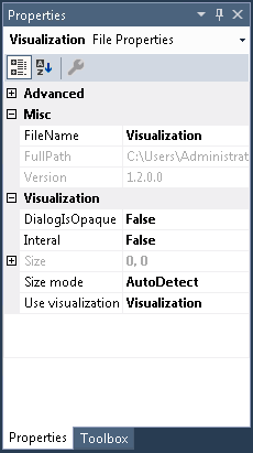
Misc
FileName | Name of the visualization object |
FullPath | Memory location of the object. The memory location cannot be changed at this point. It is therefore grayed out. |
Visualization
Dialog Is Opaque | If this setting is active the screen area hidden by this dialog is not refreshed. This has a positive effect on the drawing and input performance. Note: Use this option only if the dialog you have drawn is rectangular and fully opaque, i.e. it contains no transparent parts. |
Internal | A visualization marked as internal is visible and usable as usual inside a PLC project. If this visualization is saved in a library it is no longer visible or usable in the PLC project in which the library is used. |
Size | Size of the visualization page –the setting is grayed out if the entry "AutoDetect" has been selected under "Size mode".
|
Size mode | Here you can specify whether and how the size is to adapt to the visualization page.
If the aspect ratio resulting from these settings does not match the screen size, the visualization page is displayed with corresponding white edges. In this way distortion of the visualization elements is prevented. |
Use visualization as | In this setting one of the following visualization types can be specified for the object:
|
Editing a visualization object
The visualization editor for creating visualizations works in combination with the toolbox, which provides the visualization elements from the integrated element libraries, and the properties editor for configuring the visualization elements. To open a visualization object, double-click on the object in the project tree.
Defining a start visualization
The "start visualization", i.e. the visualization object that is to be displayed first when a PLC HMI or PLC HMI Web client is started, must be entered in the TargetVisualization or WebVisualization object.