Visualization Editor
A visualization can be created and configured with the visualization editor. The editor can be opened by double-clicking on a Visualization object in the PLC project. It features three further editors:
- Interface editor for defining placeholders
- Hotkeys configuration editor for linking actions to keys or hotkeys
- Element list, which contains a list of all elements of the visualization page that is open in the visualization editor
The elements can be shown or hidden via the menu item ‘Visualization’ or via the arrows at the top of the visualization editor.
The visualization editor is functionally extended by the toolbox, which makes the existing visualization elements available for inserting in the visualization editor, and the Properties window, in which the properties of the element that is currently highlighted in the visualization editor can be displayed and edited. They can be opened via the menu item "View".
Selecting visualization elements
A Visualization elements selected in the visualization editor shows small black squares in its frame, which can be selected with a further mouse click and moved. In this way the position and size of the element can be modified.
To select an element, pull the cursor over the element. When the cursor symbol takes the form of a hand. Press the left mouse button. Multiple selection is possible. To this end, press and hold the Shift key and select the individual elements, or draw a rectangle around the elements while pressing and holding the left mouse button. The elements can also be selected in the element list. Individual sub-elements of a group can then also be selected.
Keyboard operation
If an element is selected, the selection can be moved to the next element in the addition sequence via the tab key – or to the previous one with Shift + Tab.
Use the space bar to open a text input field in the currently selected element. Enter a string and press the Enter key to save it.
The properties of a selected element are immediately displayed in the Properties window and can be edited there. If several elements are selected, changes to the properties are applied to all elements.
Position, size, alignment, order
After the insertion of a visualization element, the following properties can be changed directly in the editor window; note that the size and position can also be edited in the Properties window.
Position | Either select the element with a mouse click and drag it directly to the required position without releasing the mouse button, or click once more on an already selected element and then move it while holding mouse button or via the arrow keys. Another option is to edit the position values in the Element properties. |
Size | Select the element, then click on one of the small squares in its frame. The cursor icon – crossed double arrows or a vertical or horizontal double arrow – indicate in which direction the size of the square can be modified. |
Alignment | To align two or more elements with each other, first select the elements you want to align. Then open the submenu "Alignment", either via the menu item "Visualization" or via by right-clicking in the visualization editor, to change the alignment. |
Order | To position one or several visualization elements in the background, the foreground or in between in the visualization, first select the element(s) you want to position. Then open the submenu "Order", either via the menu item "Visualization" or via by right-clicking in the visualization editor, to change the order. |
Grouping of visualization elements
To consolidate several visualization elements in a group, first select the elements you want to group. Then select "Group", either via the menu item "Visualization" or by right-clicking in the visualization editor, to group the elements. Once a group has been formed, subelements of the group can only be selected via the element list.
Background image
A visualization page offers an option to specify a background color and/or a background image. Right-click in the visualization editor to open a context menu from which the entry "Background" can be selected. This entry opens the following dialog:
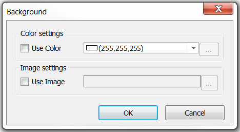
There are checkboxes for background color and background image. To select an image as a background image, it first has to be added to an image pool in the PLC project.