Input configuration
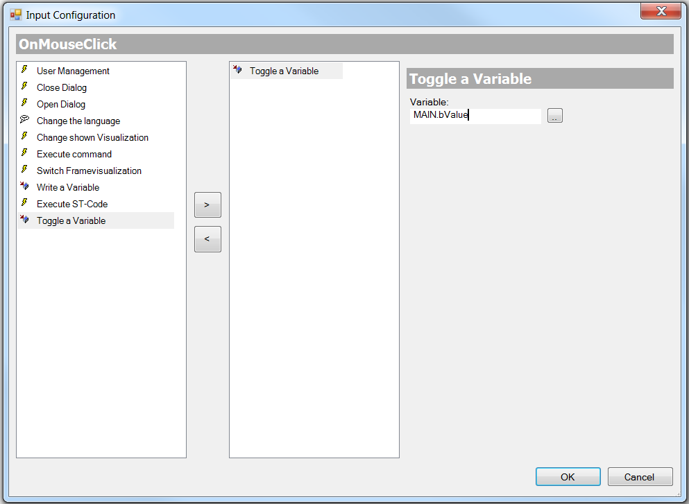
One or several of the subsequent actions described below can be defined in the input configuration dialog for a certain event (e.g. OnMouseClick). Click in the value field for this event in the Properties window to open the dialog. The name of the event, for which these subsequent actions are selected, is shown as title in the grey row.
To add a subsequent action, the corresponding action must first be selected on the left-hand side of the dialog. The action can then be added by pressing the button with the right arrow icon. To delete an action, select it on the right-hand side and press the button with the left arrow icon.
The following actions are available:
- User management
- Close dialog
- Open dialog
- Language switching
- Change shown Visualization
- Execute command
- Switch frame visualization
- Write a variable
- Execute ST-Code
- Toggle a Variable
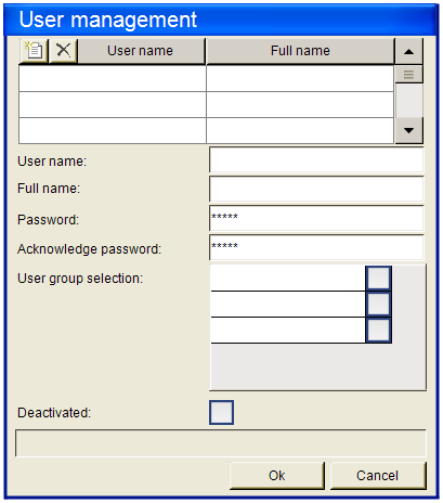
User management
User management can only be selected as subsequent action, if a User management was created first or the library "VisuUserManagement" was added manually.
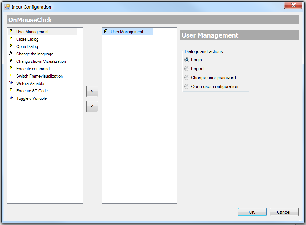
Via the user management the following four standard dialogs and actions can be added. It enables the visualization user in online mode to:
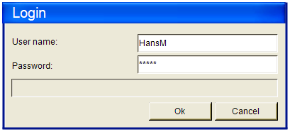
- login
- logout
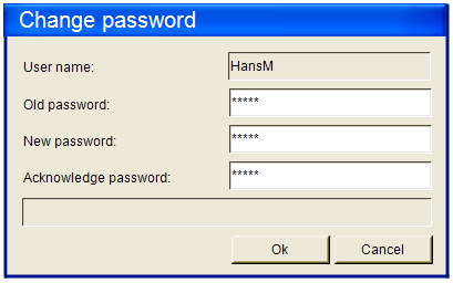
- change user password
- open user management
Close dialog
This option can be used to specify that after the event the specified dialog should be closed with the specified result. Select the required dialog from the selection list, which offers all currently available input dialogs.
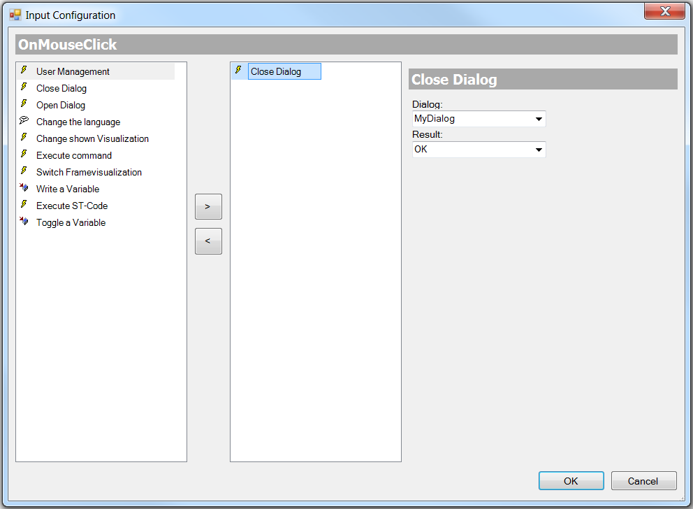
Dialog | Select a dialog from the selection list |
Result | The list offers the standard options used in dialogs. These standard options require a user response.
|
 | Not that the result from the dialog that was closed last can be retrieved, and that a corresponding response can then be configured in any element of the same visualization. Use the configuration option "OnDialogClosed" for this purpose. |
Open dialog
Here you can define that a mouse action is to be followed by opening of a dialog, which is represented by another (standard or user-created) visualization. The selection list offers all visualizations, for which the purpose "Dialog" is entered in the object properties. It enables a user-created dialog to be used as user input mask in a visualization.
As a minimum, the standard objects "VisuDialogs.Login" and "VisuDialogs.FileOpenSave" are available, if VisuDialogs.library is integrated in the project. In addition, user-created input dialogs can be used.
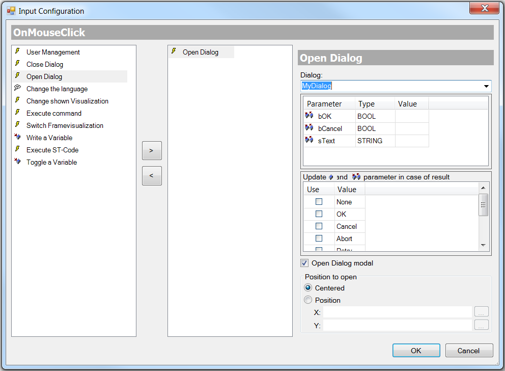
Dialog | Select a dialog from the selection list |
Parameter | For the selected dialog visualization the input (VAR_INPUT), output (VAR_OUTPUT) and input/output parameters (VAR_IN_OUT,), which were defined in the interface editor, are shown. (Parameter, Type, Value) In the last column, i.e. "Value", the parameters can be linked with variables from the PLC. The variable values are written to the parameters (VAR_INPUT, VAR_IN_OUT) when the dialog visualization is opened. (VAR_OUTPUT, VAR_IN_OUT. |
Event | The user has to specify which dialog visualization result is to be used as a basis for writing its output and input/output parameters: tick the Use column to activate the required result value. Possible values:
|
| Note that the output and input/output parameters of a dialog visualization are not written until the dialog is closed! Until then, the values are only stored on the stack, i.e. they are not treated as references but as copies. |
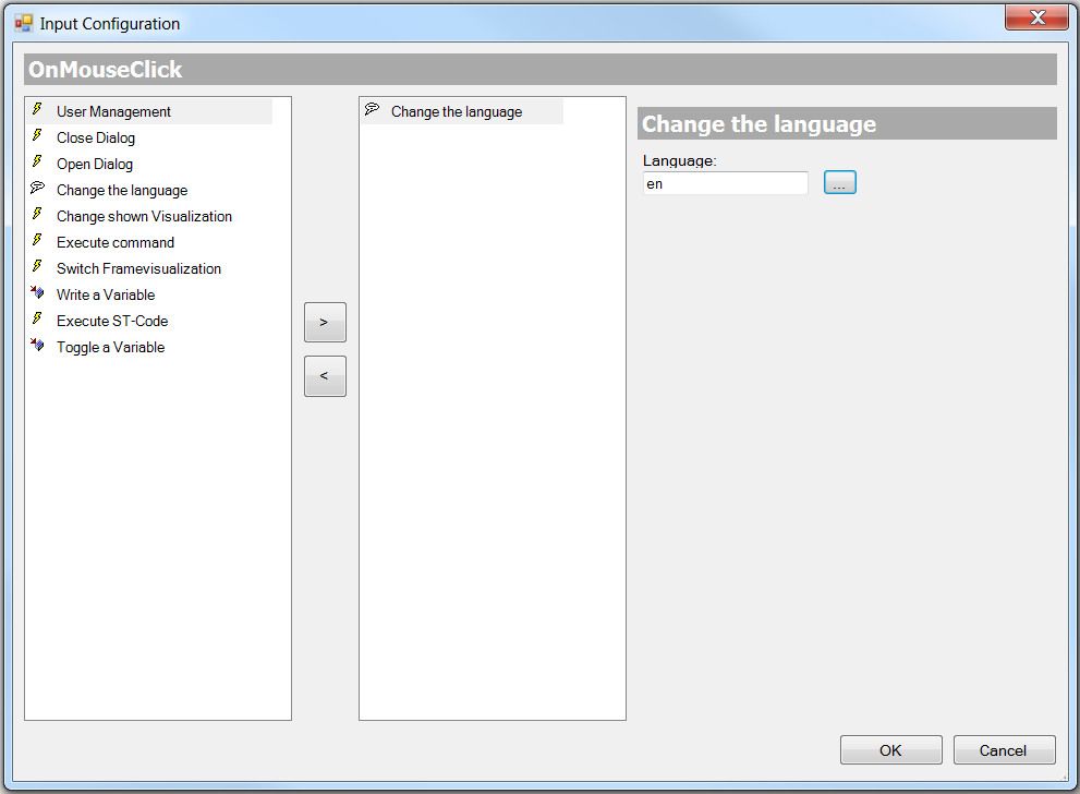
Language switching
Here you can specify an interface language for displaying the visualization texts. Use the language code, that is used in the corresponding text list(s). Alternative, click on the  button to select the required language in the input wizard. (See also Language and Text)
Change shown Visualization
Here you can select a change in the currently displayed visualization page as subsequent action. (Refer also to the section "Switching between visualization pages")
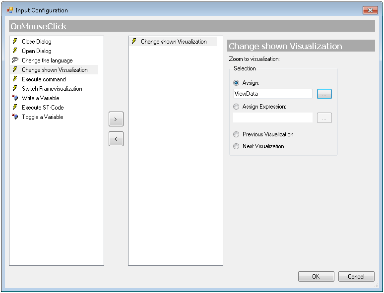
Select one of the following options to define which visualization page is to be displayed upon the mouse action in online mode:
Assign | The visualization page can entered directly. It is best to use input wizard, which can be opened via the button |
Assign Expression | Here you can specify a variable of type String, which is used by the PLC project and provides the name of the visualization page. Example: sVisualizationName : STRING := ‘MyVisualization‘; |
| The order in which the visualization pages are displayed sequentially via user inputs is stored internally. This information can be used with the following two options. |
Previous Visualization | The previously displayed visualization page is displayed again. If no visualization was called before, the current one continues to be shown. |
Next Visualization | The visualization page listed next in the recorded sequence of visualization changes is displayed. This is therefore only possible, if a previous visualization change has already taken place via "Previous Visualization". |
Execute command
Here you can define one or several commands to be executed following the mouse action.
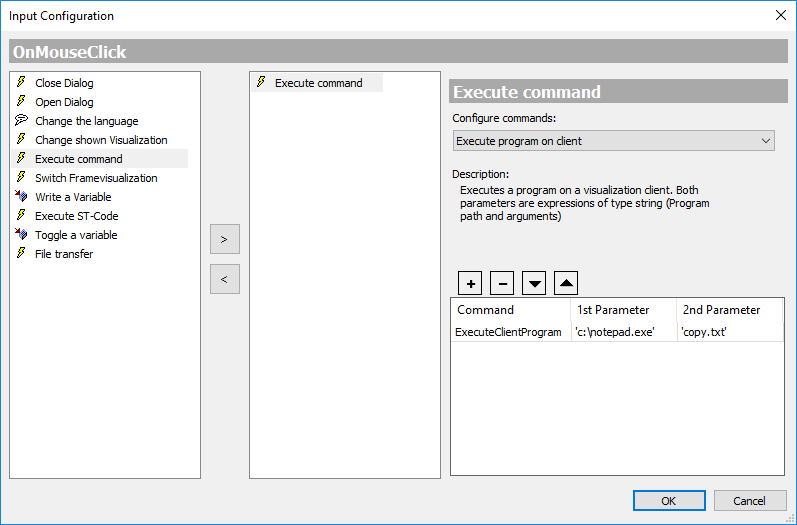
Select a command from the "Configure commands" list and press the  button to added to the table in the lower section of the dialog. This table contains all selected commands of the input configuration.
A brief description of the command selected in the list is shown in the middle section of the dialog. Add the command parameters in the table columns "1st Parameter" and "2nd Parameter". The "Command" column shows the internal command name. See also the following table for a description of the individual commands.
Use  button to remove the currently selected entry from the list. Subsequently, when the user input for the visualization element takes place, the configure commands are executed one after the other from top to bottom according to their arrangement in the table. To change the order, the entries can be moved with the
  and
and  buttons.
The following commands are available:
Execute program on controller Execute program on client | The specified program (*.exe) is executed on the controller or the visualization client. 1st parameter: string, path of the program file (example: “c:\programs\notepad.exe”) 2nd parameter: string, arguments for the program to be executed, e.g. name of a file to be opened by the program (example: copyfile.txt) |
The standard dialog "Print" is opened, where settings can be made for the setting of the printer area and the printer parameters, etc. Moreover, the current visualization can be printed out. This command is only supported within the PLC HMI under Windows. | |
Navigate to URL (WebVisu) | Requirement: visualization is executed as PLC HMI Web. When the input event occurs, the visualization navigates to the web page with the specified URL 1st parameter: Web address URL - as variable of type string, to set the start page programmatically. (Example: MAIN.sUrl) - as literal in single quotation marks. (Example: http://www.beckhoff.com 2nd parameter: If no parameter is specified, the web page is displayed in a new window or a new tab. If "replace" is specified, the PLC HMI Web is replaced with the web page. |
Switch frame visualization
Requirement: A visualization in a project has at least one frame element, which was assigned various visualizations via the Frame selection. Within the frame the visualizations are indexed 0, 1, 2, etc. By default, the first of the allocated visualizations (Index 0) is displayed online in the frame.
In the present dialog you can now link a mouse action on the current visualization element in a certain frame element with displaying a certain associated visualization. The current element can therefore be used for programming a visualization switch-over in a frame. (Refer also to the section "Switching between visualization pages within a frame")
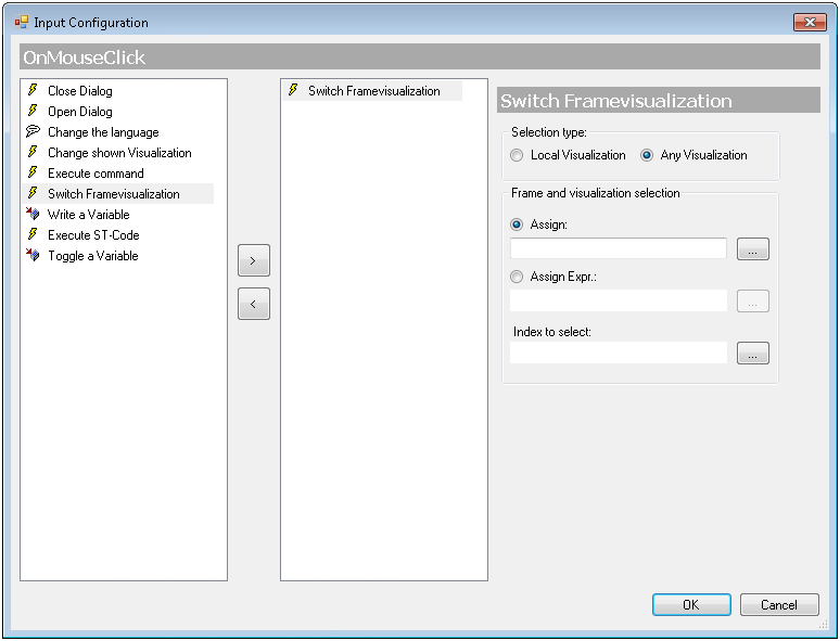
Selection type of the affected frame element
- Can be limited to the current visualization, resulting in a simpler configuration dialog, although without dynamic configuration option. (→ Local Visualization)
- Can be extended to all visualizations available in the project, including dynamic definitions of the frame and the displayed visualization (→ Any Visualization)
Local Visualization
Only frames of the current visualization can be addressed and are therefore available here in the field "Frame selection" (see below). This is a simple dialog for fast, direct configuration in the local visualization. However, it is not possible to specify the required visualization via a project variable. If this is required, select "Any Visualization".
The frame selection shows the local frame elements and indented below the associated visualizations.
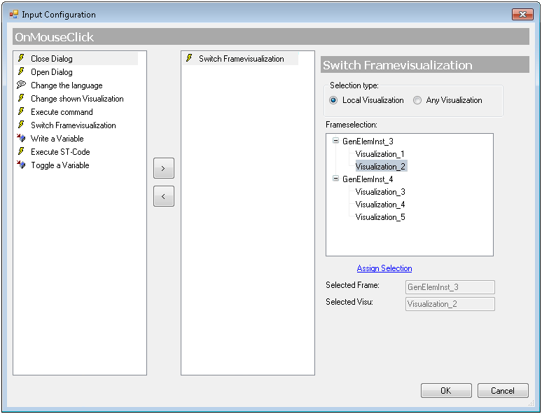
Select the required visualization from the affected frames, which is to be displayed following the mouse action. Click on "Assign Selection" to save the settings. The current selection is then displayed in the fields Selected Frame and Selected Visu.
Any Visualization
All frames of the project and their allocated visualizations are available. In this case frame and visualization can also be specified via project variables, i.e. dynamically.
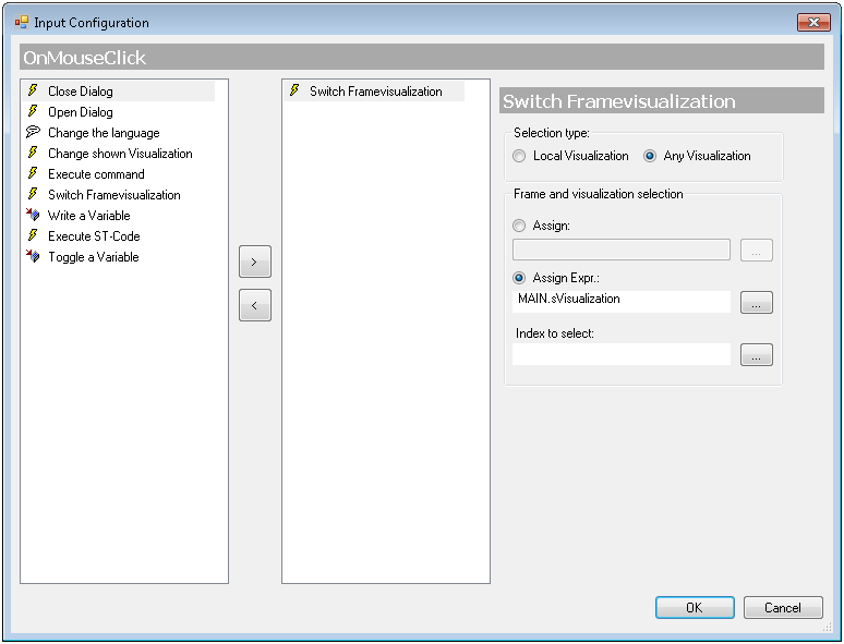
The "Frame and visualization selection" is then made via the following fields and options:
Direct assignment | If this option is enabled, the name of the affected frame element can be entered directly with the corresponding visualization. Press Example: Visualization_1.MyFrame |
Assignment via expression | This option can be enabled in order to use a project variable of type string for specifying a frame element. Press Example: sVisualization : STRING := ‘Visualization_1.MyFrame’; |
| The visualization to be displayed following the mouse action in the selected frame is specified via its index. This visualization index is an ascending integer number starting with 0, which was allocated to a frame in the frame selection. By default, the first visualization is therefore always displayed in this list initially. |
Index to select | Enter the index of the required visualization directly or via a project variable in the application. Press |
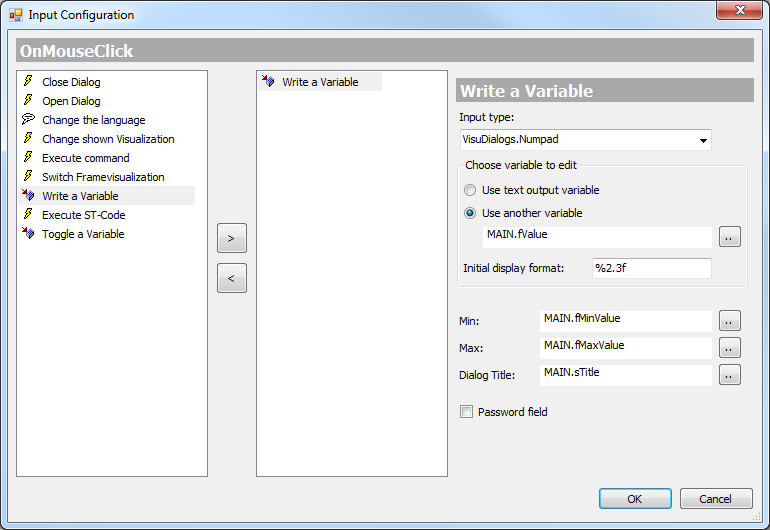
Write a variable
If an input configuration of type "Write a variable" exists for a visualization element, the element will offer an option to enter a value, as soon as the corresponding mouse action is executed. The value can then be entered as a string via a numpad or keypad and is then written to the project variable that is specified here in the input configuration dialog. The value is interpreted as text or a number, according to the data type of the project variable.
Select one of the following input types from the selection list on the right of the dialog:
Standard | The default input type is used. The default can be specified in the settings of the Visualization Manager. |
Text input | A field for the value/text input opens. A keyboard is required to enter values. |
Text input with limits | A field for the value/text input opens. In addition, the input limits are displayed at the top. They are shown in red font if they are exceeded. A keyboard is required to enter values. |
VisuDialogs.Keypad | The mouse action opens a simulated keyboard. You can enter a string by clicking on the corresponding keys. |
VisuDialogs.Numpad | The mouse action opens a simulated numpad. You can enter a number sequence by clicking on the corresponding keys. |
| In addition to the default input types, all visualizations are offered, which were defined in their properties as "numpad", "keyboard" or "dialog for input configuration". (see Object properties) |
| In order to be able to use the keypad or numpad, the library "VisuDialogs" must be added in the library manager. |
Select the variable to be edited:
Use text output variable | The value is written to the variable that is specified as text output variable in the visualization element. |
Use another variable | Specify a project variable. Press |
Initial display format | Specification of a placeholder with formatting data Example: %2.3f |
Min | Lower limit for the variable to be entered |
Max | Upper limit for the variable to be entered |
Dialog Title | Dialog title to be displayed in the dialog header, can be specified as text or via a text variable |
Password field | To show "*********" instead of the text (e.g. in the case of passwords), tick the checkbox at Password field. |
Example
Let's assume the dialog shown above is a configuration dialog for a rectangle element. If the mouse button is pressed on this rectangle in online mode, a numerical keypad appears with the title returned by the variable "MAIN.sTitle".
Click 1, 2 and 3 to enter the value "123", for example. This value is displayed in the upper part of the dialog, also the minimum and maximum values for the entry, which are specified via "MAIN.fMinValue" and "MAIN.fMaxValue". When the entry is confirmed with a mouse click on OK, "123" is written to the variable "MAIN.fValue". If "fValue" is defined as a STRING variable, it is given the value "123". If "fValue" is a numeric variable, it is assigned the value 123.
Execute ST-Code
In the input field for this subsequent action it is possible to enter code in Structured Text, which is to be executed following a mouse action.
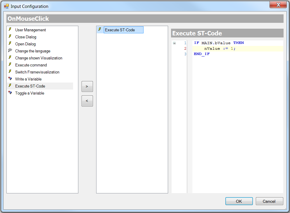
| A complex ST program is only possible if the PLC HMI and/or the PLC HMI Web is enabled. Otherwise only simple assignments are possible. |
Toggle a Variable
Here you can enter a boolean variable, which is to switch between TRUE and FALSE on repeated mouse actions.