ELM3702-0101 - Technical data
Notice | |
Extended Range mode not available The Extended Range mode is not available for RTD measurement.
|
|
Technical data |
ELM3702-0101 | |
|---|---|---|
|
Analog inputs |
2 channel (differential) | |
|
Time relation between channels to each other |
Simultaneous conversion of all channels in the terminal, synchronous conversion between terminals, if DistributedClocks will be used | |
|
ADC conversion method |
ΔΣ (deltaSigma) with internal sample rate | |
|
8 Msps | ||
|
Cutoff frequency input filter hardware |
Before AD converter: | |
|
Within AD-converter to of the transformation: | ||
|
The ramp-up time/ settling time/ delay caused by the filtering will be considered within the DistributedClocks-Timestamp. | ||
|
Resolution |
24 bit (incl. sign) | |
|
Connection technology |
2/3/4/5/6-wire | |
|
Sampling rate (per channel, simultaneous) |
Within mode TC CJC RTD (thermocouple with RTD cold junction): 500 Sps In all other modes 100 µs/10 ksps (each channel, fixed setting) Free down sampling by Firmware via decimation factor | |
|
Oversampling |
1…100 selectable (max. 10 ksps) | |
|
Supported EtherCAT cycle time (depending on the operation mode) |
DistributedClocks: min. 100 µs, max. 10 ms FrameTriggered/Synchron: min. 200 µs, max. 100 ms FreeRun: not yet supported | |
|
Input impedance |
> 500 kΩ (60 V); > 4 MΩ (other) ; 150 Ω (current) | |
|
Operation range voltage measurement |
±60/10/5/2.5/1.25 V, 2-wire-connection | |
|
Operation range current measurement |
±20 mA, 0/4…20 mA, NAMUR NE43, 2-wire-connection | |
|
Operation range SG, measuring bridge |
Full bridge |
Full bridge (±2/4/8/32 mV/V), 4/6-wire-connection, Bridge supply adjustable, 120 … 5000 Ω possible |
|
Half bridge |
Half bridge (±2/16 mV/V), internal switched bridge extension, 3/5-wire-connection Bridge supply adjustable, 120 … 5000 Ω possible | |
|
Quarter bridge |
Quarter bridge 120 Ω ,350 Ω and 1000 Ω (±2/4/8/32 mV/V), internal switched bridge extension, 2/3-wire-connection, Bridge supply adjustable | |
|
Operation range IEPE |
Measuring ranges ±2.5/5/10 V adjustable, Current supply/ / IEXCITE (IEPE Bias Current) 2 mA (shutdown not possible), Acquisition of the modulated alternating voltage, AC/DC coupling (parameterizable high pass), 2-wire-connection | |
|
Operation range potentiometer |
Potentiometer ≥ 1 kΩ, power supply integrated and adjustable 0…5 V, 3/5-wire-connection | |
|
Operation range resistance measurement |
0…50 Ω, 0…200 Ω, 0…500 Ω, 0…2 kΩ, 0…5 kΩ, Fixed set supply voltage 2.5 V at 5 kΩ, 2 kΩ; 4.5V at 500 Ω, 200 Ω, 50 Ω; internal reference resistance 5 kΩ 2/3/4-wire-connection | |
|
Operation range temperature (RTD) |
Pt100, Pt200, Pt500, Pt1000, Ni100, Ni120, Ni1000, div. KT/KTY (types see documentation), 2/3/4-wire-connection | |
|
Operation range temperature (thermocouple) |
Typ A, Au/Pd, B, C, D, E, G, J, K, L, N, PLII, Pt/Pd, R, S, T, U cold junction measurement: internal (terminal), internal (connection) and external 2-wire-connection | |
|
Connection diagnosis |
Wire break/short cut | |
|
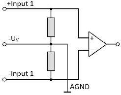
Internal analog ground AGND |
Existing by external connection to -Uv | |
|
Overvoltage protection of the inputs related on ‑Uv (internal ground) |
tbd. | |
|
Internal power supply |
via E-bus | |
|
Current consumption E-bus |
typ. 580 mA | |
|
Current consumption power contacts |
- | |
|
Thermal power dissipation |
typ. 3 W | |
|
Dielectric strength – destruction limit |
Maximum permitted voltage between +/- Input1 and –Uv (each channel) |
±35 V |
|
Maximum permitted voltage between +/- Input2 and –Uv (each channel) |
±35 V | |
|
Recommended operation voltage range to compliance with specification |
Maximum permitted voltage between +/- Input1 and –Uv (each channel) |
±33 V within ±60 V measuring range ±10 V in all other measurement ranges
|
|
Maximum permitted voltage between +/- Input2 and –Uv (each channel) |
±5 V | |
|
Common data |
ELM3702-0101 |
|---|---|
|
Distributed Clocks |
Yes, with Oversampling n = 1…100, accuracy << 1 μs |
|
Special features |
Extended Range 107 %, freely configurable numeric filters, TrueRMS, integrator/differentiator, non-linear scaling, PeakHold |
|
Functional diagnosis 1) |
Yes |
|
Electrical isolation channel/channel 2) |
Functional insulation, 707 V DC (type test) |
|
Electrical isolation channel/E-bus 2) |
Functional insulation, 707 V DC (type test) |
|
Electrical isolation channel/GND 2) |
Functional insulation, 707 V DC (type test) |
Configuration | via the EtherCAT Master, e.g. TwinCAT |
Note to cable length | Signal cable lengths to the sensor / encoder over 3 m must be shielded, the shield design must be in line with the state of the art and be effective. For larger cable lengths > 30 m, a suitable surge protection should be provided if appropriate interference could affect the signal cable. |
1) see chapters Self-test and self-test report and Connection test/switchable connection diagnosis
2) see notes to potential groups within chapter Power supply, potential groups
Basic mechanical | ELM3702-0101 |
|---|---|
Connection type | LEMO 1B 308 8-pin |
Dimensions (W x H x D) | See chapter Housing |
Mounting | on 35 mm rail conforms to EN 60715 |
Note mounting | Plug partly not within scope of delivery, see chapter |
Weight | Approx. 350 g |
Permissible ambient temperature range during operation | 0…+55 °C |
Permissible ambient temperature range during storage | -25…+85 °C |
Environmental data | ELM3702-0101 |
|---|---|
Permissible operating altitude range | 0 up to 2000 m (derating at higher altitudes on request) |
Relative humidity | max. 95%, no condensation |
Protection class | IP 20 |
Installation position | Variable |
Normative data | ELM3702-0101 |
|---|---|
Vibration-/shock resistance | Conforms to EN 60068-2-6 / EN 60068-2-27 |
EMC-resistance / emission | Conforms to EN 61000-6-2 / EN 61000-6-4 |
Approvals/ markings *) | CE, UKCA, cULus_60, EAC |
*) Real applicable approvals/markings see type plate on the side (product marking).
- ELM3702-0101 overview measurement ranges
- Measurement 5V/ 10V/ ±20 mV..±60 V
- Measurement ±20 mA/ 0..20 mA/ 4..20 mA/NAMUR
- Measurement resistance
- RTD measurement
- Potentiometer measurement
- Measurement SG 1/1 bridge (full bridge) 4/6-wire connection
- Measurement SG 1/2 bridge (half bridge) 3/5-wire connection
- Measurement SG 1/4-Bridge (quarter bridge) 2/3-wire connection
- Measurement IEPE 10 V / 20 V / ±2.5 V / ±5 V / ±10 V
- Thermocouple measurement