Potentiometer measurement
The potentiometer should be supplied via the integrated power supply unit (max. 5 V, configurable). The slider voltage is then measured in relation to the supply voltage and given as a percentage. Technically, the measurement process is similar to a half-bridge strain gauge.
In the following, the specification is given for a 5-wire configuration; external line resistances are compensated for by the 5-wire configuration and the potentiometer is recorded directly in the measuring channel. In the 3-wire configuration, the measuring channel essentially meets the same specification, as it continues to measure internally in 5-wire configuration. However, the lead and contact resistance levels in cables and plugs, which are usually unclear and temperature-dependent, must be taken into account by the connected potentiometer, as they affect measurement. The entire "potentiometer + supply lines + measuring channel" system in the 3-wire configuration will therefore not be able to achieve the specification values listed below.
Potential diagnoses at full-scale deflection or 0 display:
- slider break
- interruption in supply
Potentiometers from 500 Ω can be used.
The specification and the manufacturer's calibration were determined with a 5 kΩ potentiometer. If a different potentiometer resistance is used, the measurements will be incorrect due to the changed parallel circuit ratios, see "Supply, potential groups" chapter.
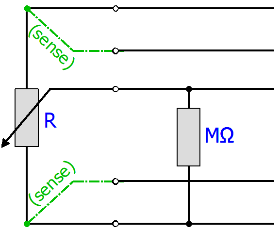
The distortion can also be recorded mathematically:
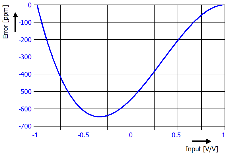 Fig.101: difference between 500 Ω and 5 kΩ potentiometer
 | Using the sample programs This document contains sample applications of our products for certain areas of application. The application notes provided here are based on typical features of our products and only serve as examples. The notes contained in this document explicitly do not refer to specific applications. The customer is therefore responsible for assessing and deciding whether the product is suitable for a particular application. We accept no responsibility for the completeness and correctness of the source code contained in this document. We reserve the right to modify the content of this document at any time and accept no responsibility for errors and missing information. |
The following example code can be used to theoretically correct a different potentiometer:
VAR
    R_Poti_calibration : LREAL := 5000.0; // Ohm (vendor calibration case)
    R_Poti_actual : LREAL := 500.0; // Ohm (user application case)
    Rin : LREAL := 2.06E6; // Ohm
    PDO : LREAL; // RAW Value
    PDO_Ratio : LREAL;
    R2_act : LREAL;
    R1_act : LREAL;
    R2_act_Rin_parallel : LREAL;
    R2_calibration : LREAL;
    R1_calibration : LREAL;
    R2_calibration_Rin_parallel : LREAL;
    PDO_corrected : LREAL;
END_VAR
PDO_Ratio := PDO / 7812500.0;
R2_act := R_Poti_actual / 2.0 - PDO_Ratio * R_Poti_actual / 2.0;
R1_act := R_Poti_actual / 2.0 + PDO_Ratio * R_Poti_actual / 2.0;
IF (R2_act + Rin) <> 0 THEN
            R2_act_Rin_parallel := (R2_act * Rin) / (R2_act + Rin);
ELSE
            R2_act_Rin_parallel := 0.0;
END_IF
R2_calibration := R_Poti_calibration / 2.0 - PDO_Ratio * R_Poti_calibration / 2.0;
R1_calibration := R_Poti_calibration / 2.0 + PDO_Ratio * R_Poti_calibration / 2.0;
IF (R2_calibration + Rin) <> 0 THEN
            R2_calibration_Rin_parallel := (R2_calibration * Rin) / (R2_calibration + Rin);
ELSE
            R2_calibration_Rin_parallel := 0.0;
END_IF
IF (R1_act + R2_act_Rin_parallel) <> 0 AND R_Poti_actual <> 0 AND (R1_calibration + R2_calibration_Rin_parallel) <> 0 AND R_Poti_calibration <> 0 THEN
            PDO_corrected := (PDO_Ratio-
                        (((2.0*(0.5-R2_act_Rin_parallel/(R1_act+R2_act_Rin_parallel)))-
                        (2.0*(0.5-R2_act/R_Poti_actual)))-
                        ((2.0*(0.5-R2_calibration_Rin_parallel/(R1_calibration+R2_calibration_Rin_parallel)))-
                        (2.0*(0.5-R2_calibration/R_Poti_calibration)))))*7812500.0;
ELSE
            PDO_corrected := 0.0;
END_IF
Measurement mode | Potentiometer (3/5-wire) |
|---|---|
Operation mode | The supply voltage is configurable via CoE, |
Measuring range, nominal | -1 … 1 V/V |
Measuring range, end value (FSV) | 1 V/V |
Measuring range, technically usable | -1 …1 V/V |
PDO resolution | 24 bit (including sign) |
PDO LSB (Extended Range) | 0.128 ppm |
PDO LSB (Legacy Range) | 0.119… ppm |
Specific data (not valid for ELM3704-1001)
Note: specifications apply to 5 V excitation and potentiometer 5 kΩ.
Measurement mode | Potentiometer (3/5-wire) | |||
|---|---|---|---|---|
Basic accuracy: Measuring deviation at 23°C, with averaging, typ. 2) 6) | without Offset | < ±0.0025 %FSV | ||
incl. Offset | < ±0.0075 %FSV | |||
Extended basic accuracy: Measuring deviation at 0…55°C, with averaging, typ. 2) 6) | without Offset | < ±0.0075 %FSV | ||
incl. Offset | < ±0.0105 %FSV | |||
Offset/Zero point deviation (at 23°C) | EOffset | < 70 ppmFSV | ||
Gain/scale/amplification deviation (at 23°C) | EGain | < 20 ppm | ||
Non-linearity over the whole measuring range | ELin | < 15 ppmFSV | ||
Repeatability, over 24 h, with averaging | ERep | < 1 ppmFSV | ||
Temperature coefficient, typ. | TcGain | < 2 ppm/K | ||
TcOffset | < 1 ppmFSV/K < 1.0 µV/V/K | |||
Noise (without filtering, at 23°C) | ENoise, PtP | < tbd. ppmFSV | ||
ENoise, RMS | < tbd. ppmFSV | |||
Max. SNR | > tbd. dB | |||
Noisedensity@1kHz | < tbd. | |||
Noise (with 50/60 Hz FIR filter, at 23°C) 5) | ENoise, PtP | < tbd. ppmFSV | ||
ENoise, RMS | < tbd. ppmFSV | |||
Max. SNR | > tbd. dB | |||
Common-mode rejection ratio (without filter) 3) | DC: | 50/60 Hz: | 1 kHz: | |
Common-mode rejection ratio (with 50/60 Hz FIR filter) 3) 5) | DC: | 50/60 Hz: | 1 kHz: | |
Largest short-term deviation during a specified electrical interference test | tbd. %FSV = tbd. ppmFSV typ. | |||
Input impedance (internal resistance)
| typ. approx. 2.06 MΩ || 100 pF against AGND typ. approx. 20 nF against SGND | |||

 typ.
typ. typ.
typ.2) A regular offset adjustment with connected potentiometer is recommended. The given offset specification of the terminal is therefore practically irrelevant. Therefore, specification values with and without offset are given here. In practice, the offset component can be eliminated by the functions Tare and also ZeroOffset of the terminal or in the controller by a higher-level tare function. The offset deviation over time can change, therefore Beckhoff recommends a regular offset adjustment or careful observation of the change.
3) Values related to a common mode interference between SGND and internal ground.
5) the 50/60 Hz filter setting must be selected via the settings in the CoE depending on the local mains frequency (50 or 60 Hz); the respective nominal mains frequency then applies as the measuring point for common mode rejection or crosstalk.
6) Calculated value according to the equation for estimating usability at the given ambient temperature point or estimating usability over the specified ambient temperature range in operation (Tambient) as stated in chapter "General information on measuring accuracy/measurement uncertainty". In real use, for example at a relatively constant ambient temperature Tambient, a lower (better) achievable uncertainty is attained. A specific calculation according to chapter "General information on measuring accuracy/measurement uncertainty" is recommended, especially if the instrument allows a wider ambient temperature range in operation than 0...55 °C.
Specific data (not valid for ELM3704-10x1):
Measurement mode | ±20 mA, 0…20 mA, 4…20 mA, NE43 | |
|---|---|---|
Basic accuracy: Measuring deviation at 23°C, with averaging 3) 6) | < ±0.008 %, < ±80 ppmFSV typ. < ±1.6 µA typ. | |
Extended basic accuracy: Measuring deviation at 0…55°C, with averaging 3) 6) | < ±0.0135 %, < ±135 ppmFSV typ. < ±2.7 µA typ. | |
Offset/Zero point deviation (at 23°C) 3) | EOffset | < 25 ppmFSV |
Gain/scale/amplification deviation (at 23°C) 3) | EGain | < 60 ppm |
Non-linearity over the whole measuring range 3) | ELin | < 45 ppmFSV |
Repeatability, over 24 h, with averaging 3) | ERep | < 10 ppmFSV |
Temperature coefficient 3) | TcGain | < 3 ppm/K typ. |
TcOffset | < 1.5 ppmFSV/K typ. < 30 nA/K typ. | |
Potentiometer measurement range
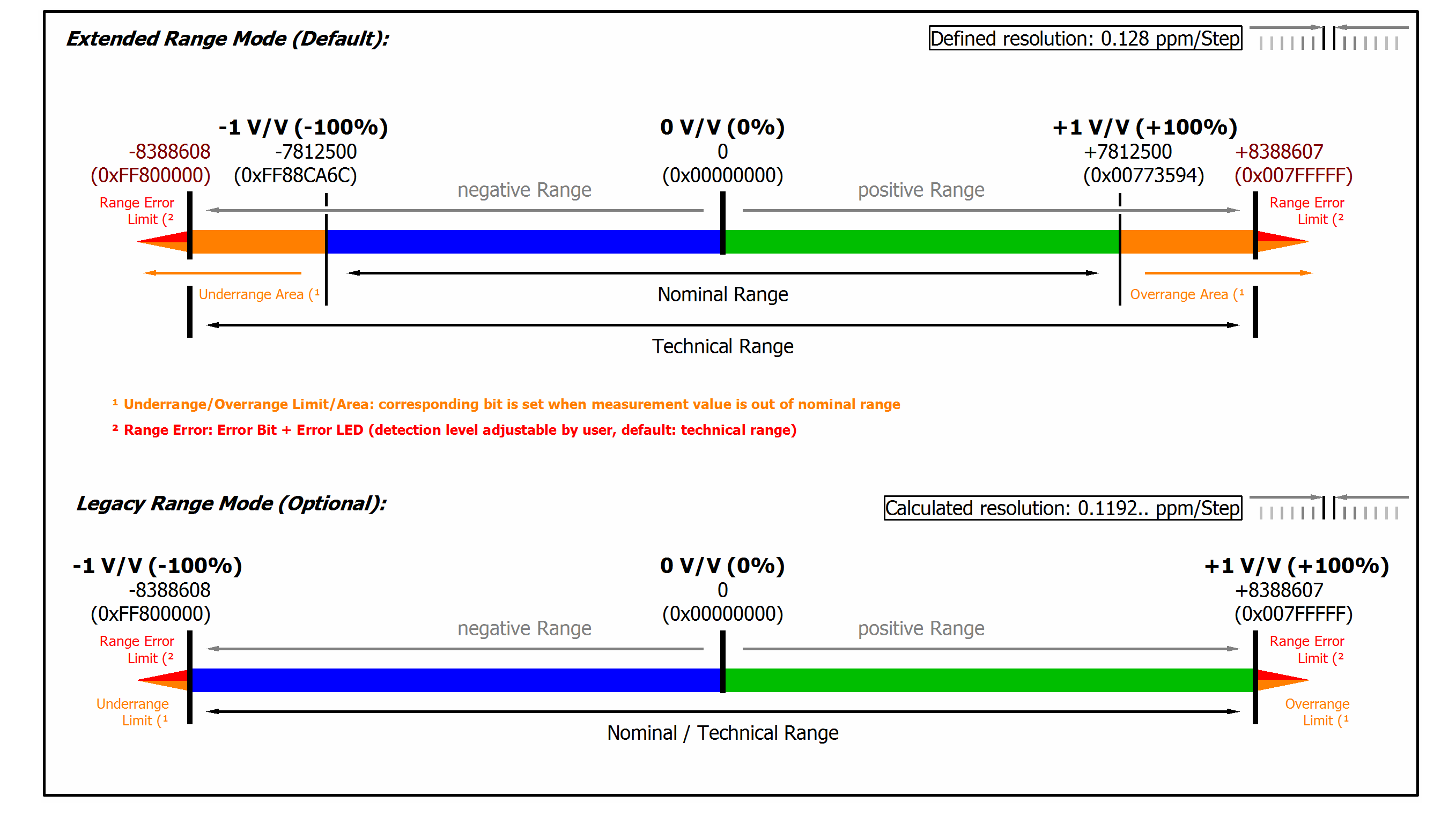 Fig.102: Representation potentiometer measurement range
|
Note: In Extended Range Mode the Underrange/Overrange display in the PDO status has the character of an information/warning when the nominal measuring range is exceeded, i.e. no Error is displayed in the PDO status and LED. If the technical measuring range is also exceeded, Error = TRUE is also displayed. The detection limit for Underrange/Overrange Error can be set in the CoE. In Legacy Range mode, an Underrange/Overrange event also leads to an Error in the PDO status. |