Output function
Two 24 VDC digital outputs can be parameterized and switched independently of each other (n = 0 for output 1, n = 1 for output 2).
The following options are available for parameterization:
- Set switching characteristics:
Push-Pull or Push-Tristate mode - Set state in case of bus error:
Definition of the safe state of the output in case of a bus error
Furthermore, the following options are available for switching the outputs:
- 1. With disabled automatic switching function
("Control_enable thresholds output" 0x70n1:02 = FALSE)
- via PLC variable:
The output can be set from the PLC application.
- 2. With active automatic switching function
("Control_enable thresholds output" 0x70n1:02 = TRUE)
- when specified counter values are reached:
- Up to eight threshold values ("Threshold 1" - 8) can be specified for switching per output.
- The status of the output TRUE or FALSE can be selected as desired ("Output state 1" - 8).
- Furthermore, it is possible to switch the outputs for defined times ("Duration 1" - 8) when predefined values are reached.
- A timestamp function is available for the outputs when the threshold value (Threshold n) is reached.
Observe the notes in the chapter Timestamp function for outputs! - The implementation of a digital cam controller is possible.
- when specified frequency or velocity values are reached:
- Up to two threshold values are available per output.
- The status of the outputs is fixed:
"Threshold 1": "Output state 1" = TRUE
"Threshold 2": "Output state 2" = FALSE - The function to switch outputs for a defined time (duration) is not available for specified frequency and velocity values.
- A timestamp function is available for the outputs when the threshold value (Threshold n) is reached.
Observe the notes in the chapter Timestamp function for outputs!
Value specification and output data via the process data
The value specification takes place in each case via the process data. This allows very short reaction times, independent of the PLC cycle.
The output data of the outputs are displayed in the area of the "ENC Control Output Channel n", the corresponding feedbacks or status information under "ENC Status Output Channel n" (see following figure)
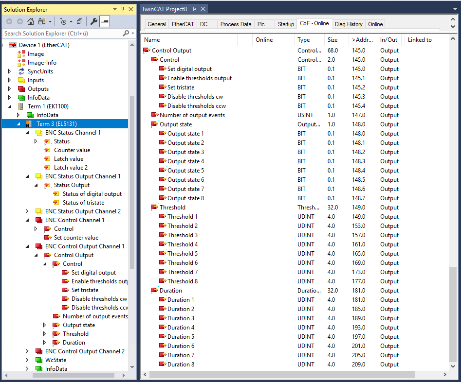
Display of the output data