Commissioning of the temperature control
The commissioning of the temperature control includes both a TwinCAT Engineering and a part to be executed at runtime. This sample summarizes the steps that are executed at runtime.
 | Commissioning via HMI recommended This sample describes the procedure solely via the PLC path. Use the section Commissioning of the temperature control for commissioning using the HMI. |
Before the subsequent steps, the preparation of the TwinCAT project has to be done according to the example from section Mapping and configuration of temperature zones.
Set the appropriate input and output signal types and devices for all your temperature zones
| Hardware parameterization without grouping This step refers to the linear mapping of the TF8540 library. Already configured groupings are ignored in this step. |
- 1. Create a program section to assign the parameters once.
- 2. Assign the following parameters according to your hardware configuration.
// set cooling output type to "no cooling"
fbTemperature.Channels(1).OutputSel_C  := E_TcPfw_TctrlOutSelect.eTcPfwTcOut_NoSignal;
// set heating output type to "pwm"
fbTemperature.Channels(1).OutputSel_H  := E_TcPfw_TctrlOutSelect.eTcPfwTcOut_PWM;
// set sensor terminal type to "EL3314"
fbTemperature.Channels(1).TempSensTerm := E_TcPfw_TerminalType.eTcPfwTermT_EL331x;
// set sensor type to "ThermoCouple Typ K"
fbTemperature.Channels(1).SensorType   := E_TcPfw_TempSensType.eTcPfwTempSensT_TC_K;
// set terminal channel of the sensor to "Channel 1"
fbTemperature.Channels(1).TermChannel := 1;- 3. Repeat step 2 for all channels used. If necessary, use a
FORloop or the FB_Temperature.CreateDefaultParams() method to assign an identical parameter for multiple zones.
FOR i := 3 TO MIN(5, fbTemperatureHmi.CountPfwChannels) DO
    fbTemperature.Channels(i).OutputSel_C := E_TcPfw_TctrlOutSelect.eTcPfwTcOut_PWM;
END_FOR- 4. Execute the created code segment once.
- 5. Log on to the controller.
- 6. Save the parameters on your target device via
fbTemperature.MachineData.Save.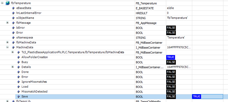
Check the reaction of the hardware inputs on the machine
- 1. Log on to the controller.
- 2. Go in the tree structure
fbTemperature.aGroups[…].aZones[…]to the first used zone. - 3. Heat the sensor of the zone via an external heat source.
- 4. Observe via the value
ActualTemperaturewhether the temperature change occurs in the expected zone.
Repeat step 2 to 4 for each zone.
Check the response of the hardware outputs on the machine
| Switching on a zone does not generate a power level Make sure that at the time of this step the temperature control has been enabled by the PLC!
|
- 1. Switch on a single temperature zone via
fbTemperature.aGroups[…].Zones[…].Enable. - 2. Check if in the same zone the value of the variable
Heating=TRUEand the value of the variableActualTemperaturechanges. - 3. Switch the zone off again as soon as possible to keep the temperature rise to a minimum.
- 4. Repeat steps 1 to 3 for each zone.

Start the automatic tuning of the control parameters
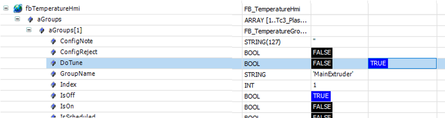
- 1. Activate the tuning of a group via
fbTemperatureHmi.aGroups[…].DoTune= TRUE. - 2. Execute step 1 for all groups to be commissioned.
Monitor the automatic tuning until it completes successfully
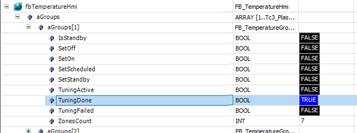
- 1. As soon as the value of the variable
fbTemperatureHmi.aGroups[…].TuningActiveis reset, the tuning of the group is finished. - 2. The value of the variable
fbTemperatureHmi.aGroups[…].TuningDoneindicates whether the tuning was successful.
- You have successfully commissioned your temperature control.