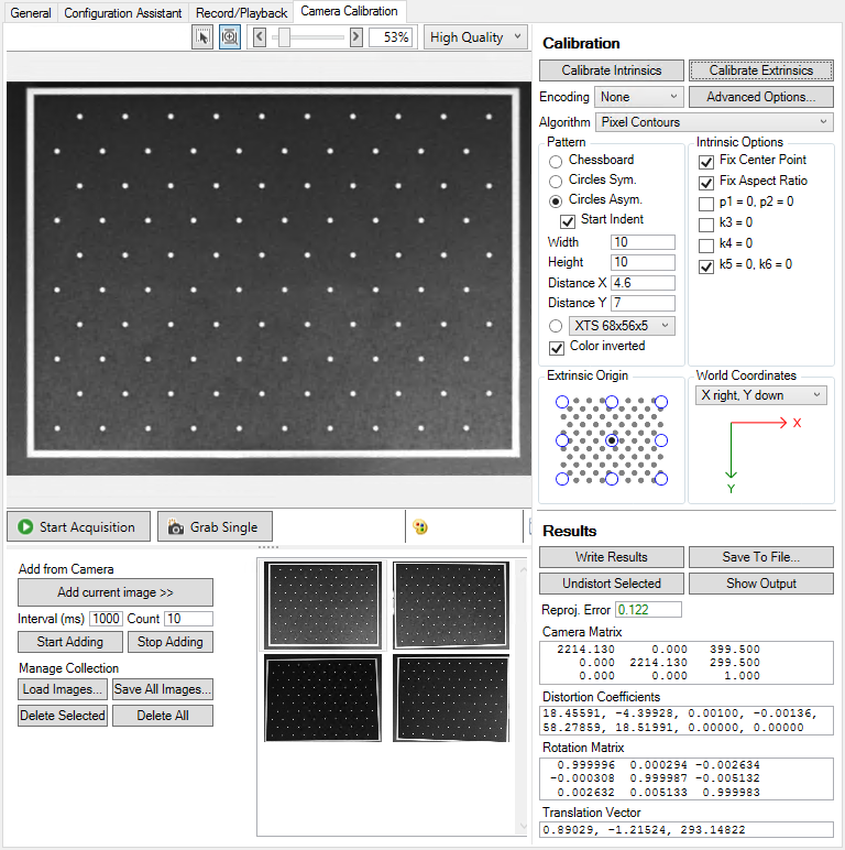
Camera Calibration
Area scan cameras can be geometrically calibrated with the help of a calibration pattern on the Camera Calibration tab.
During geometric camera calibration of area scan cameras, the imaging process is reconstructed from the image. For this purpose, points in the image are required whose positions in the real world are known. Calibration patterns with defined points are available from which images are taken.
Supported calibration patterns:
Image acquisition / selection
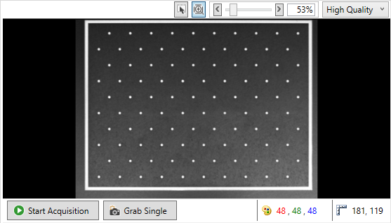
As in the Configuration Assistant there is a preview image for the image acquisition above which there are display options and below which there are controls for the image acquisition:
 | Displaying the preview image The image is always displayed just as it is received from the camera. An image in the Bayer format will therefore be displayed unencoded as a grayscale image. At this point the set encoding is not yet applied to the image. The encoding is relevant only for the calibration process, but not for the preview image. |
Above the preview window:
- Interpolation of the preview image:
Combo box for selecting whether a high-quality or nearest-neighbor interpolation of the preview image should be performed. The selection only refers to the preview. The calibration is based on the original image data. - Size of the preview image
If Fit to window is selected, the image is scaled to the size of the preview window. Alternatively, a display size can be specified via the slider.
Below the preview window:
- Start Acquisition / Stop Acquisition
Button for starting or stopping image acquisition. Streaming mode of the camera must be active. - Grab Single
Button for triggering a single image. - Pixel Value
Shows the color value of the pixel at the mouse cursor position on the image. - Cursor Position
Shows the mouse cursor position on the image. Please note that the zero point for images is always at the top left.
If the calibration pattern is within the camera's field of view, the corresponding image can be selected for calibration. The Controls are located below the preview image on the left, the collection of images for calibration on the right.
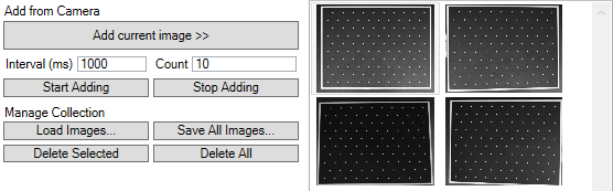
- Add current image >>
Add current image adds the currently displayed camera image to the collection for calibration. - Start / Stop Adding
Instead of a single image, a series of images can be added to the collection. The image series is started via Start Adding. Subsequently, images are added at intervals of the time set for Interval until the number entered for Count is reached or the addition of images is terminated via Stop Adding. - Load Images...
As an alternative to image acquisition, saved images can be loaded via Load Images. Note here that these were recorded with the same camera system, the same camera settings, the same lens settings and the same calibration pattern. - Save All Images...
Save All Images can be used to save the complete image collection. - Delete Selected
Delete Selected deletes the selected images from the collection. - Delete All
Delete All deletes all images from the collection.
| Image format At this point only Mono8, RGB24 and Bayer8 images may be used. |
Settings and calculations
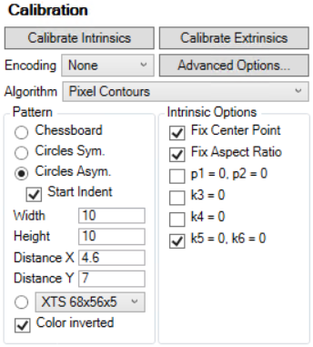
Encoding
For measurement tasks we recommend using a monochrome camera. However, if it should be necessary to calibrate a color camera with Bayer pattern, the corresponding Bayer pattern must be specified by Encoding. This is automatically selected by default.
Algorithm
For circle pattern detection, you can choose between different edge localization functions. The subpixel function can be used to improve the result depending on the image quality. However, this also means that the entire process takes more time. See the chapter Measurement for more information on the subpixel functionality.
- Pixel Contours
Contour-based - Subpixel Interpolation
With Subpixel by interpolation - Subpixel Erf Approximation
With Subpixel after Erf Approximation
Definition of the calibration pattern
The calibration pattern used is selected and defined under Pattern:
- Chessboard
A chessboard pattern is used - Circles Sym.
A symmetrical circles pattern is used - Circles Asym.
An asymmetrical circles pattern is used - Start Ident
Checkbox to specify indentation of the first row of the circle pattern. In the standard system without a check mark, a row that is not indented is expected. - Width
Number of feature points in horizontal direction - Height
Number of feature points in vertical direction - Distance X
Distance in the world coordinate system of the feature points in horizontal direction - Distance Y
Distance in the world coordinate system of the feature points in vertical direction - Drop-down menu for individual circle patterns
Selection of an individual circle pattern (entries are only displayed if corresponding files are found in the specified folder) - Color inverted
Checkbox for selecting color inversion of the image. By default (no check mark), black objects are expected on a white background.
| Symmetrical pattern In the case of wholly symmetric patterns, the assignment of the points found may deviate from those defined or the coordinate origin may lie in a different quadrant. This can also occur if the pattern from the selected image is in a different orientation to that defined. Therefore, after completion of the calibration procedure, you should check whether the coordinate system corresponds to your specification. |
| Check for filled circles In the case of circle patterns, an additional check is made to see whether the circles are filled in the corresponding color. If deviations occur at this point, the corresponding point is not recognized as part of the pattern. |
For information on patterns and parameter settings, please refer to the supported calibration pattern types:
Intrinsic Options
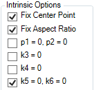
- Fix Center Point: the principle point corresponds to the center of the image.
- Fix Aspect Ratio: the camera sensor is assumed to have square pixels, so that the aspect ratio of the pixels is the same in the x and y directions.
- p1=0, p2=0: it is assumed that no tangential distortions exist, and the corresponding coefficients are set to 0.
- k3=0: the radial distortion coefficient k3 is assumed to be 0
- k4=0: the radial distortion coefficient k4 is assumed to be 0
- k5=0, k6=0: the radial distortion coefficients k5 and k6 are assumed to be 0
Extrinsic Origin
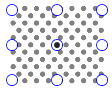
Extrinsic Origin specifies the origin point of the world coordinate system in the calibration pattern.
Depending on the selected calibration pattern, a corresponding background image is displayed.
| Origin The selected origin refers to the corresponding point of the calibration pattern, not to the complete image. |
World Coordinates
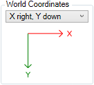
World Coordinates sets the orientation of the world coordinate system. This can be used to set a different orientation compared to the image coordinate system. With the default setting shown, the two coordinate systems match.
Actions
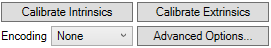
Calibrate Intrinsics
Calibrate Intrinsics calculates the camera matrix and the distortion coefficients. All images of the selection are used for this purpose. These must all contain the defined calibration pattern in its entirety. If this is not the case, a negative Reproj. Error is displayed.
Calibrate Extrinsics
Calibrate Extrinsics calculates the rotation matrix and the translation vector. A prerequisite for this is the intrinsic calibration (camera matrix and distortion coefficients) and selection of the image where the points of the 2D calibration pattern are located in the subsequent measuring plane.
| Duration of a calibration The duration of a calibration increases with the number of reference points in the calibration pattern and the number of calibration images. Therefore, when choosing a calibration pattern, make sure that the duration remains within acceptable limits for you. |
| Deviation of the results On account of the algorithm used, the results of the calibration may differ slightly from one another in the decimal place range from call to call. This concerns both the results of the calibration in the calibration assistant and those in the PLC as well as between both calibration variants. |
| Transfer of the settings into the TwinCAT project The set values and options are only applied to the TwinCAT project after executing the Calibrate Intrinsics or Calibrate Extrinsics function. If the project is saved afterwards, these values will be reloaded when it is opened again. Otherwise, the default settings are always used. |
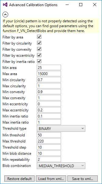
Advanced Options
Circle pattern recognition can be reparameterized via the Advanced Calibration Options. This should only be done if there are difficulties with the default settings. For a better understanding of the setting parameters, see the parameterization of the function F_VN_DetectBlobs.
Results
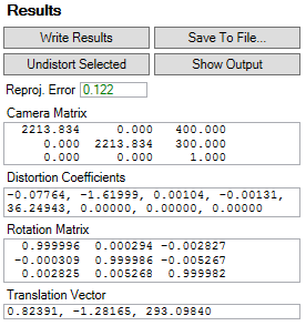
Reproj. Error
The Reprojection Error indicates the result of the intrinsic calibration:
- >0: valid result
- <1: good result
- >2: inaccurate result
- <0: no result and specific error number:
- -100: no image found
The collection of images below the preview window is used for the intrinsic calibration. The live image of a camera is not taken into account. - -200: the pattern could not be found in at least one image.
All images in the collection below the preview window must show the complete pattern, including all feature points. For a better analysis, result images are created under C:\ProgramData\Beckhoff\Vision\_CalibrationAssistantOutput, which show the feature points that were found. - -300: none of the existing images contains the selected pattern.
See description for -200, in addition, we recommend checking the pattern configuration. - -400: the user-defined description file for an individual calibration pattern is invalid.
- -500: an error has occurred.
Camera Matrix
The camera matrix describes the imaging process from 3D to 2D.
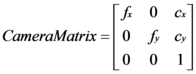
- The parameters fx and fy indicate the focal length in the x and y directions.
- The parameters cx and cy indicate the intersection point of the optical axis with the image, which is referred to as the principal point. Ideally, this should be in the center of the image. If Fix Center Point is selected under Intrinisic Options, the parameters cx and cy are automatically set to the center of the image.
Distortion Coefficients
Aberrations of the optical system can lead to distortions in the image. These can be partly compensated by the Distortion Coefficients during the coordinate transformation.

- The coefficients k1 to k6 describe the radial distortions in the image.
- The coefficients p1 and p2 describe the tangential distortions in the image.
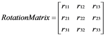
Rotation Matrix
The rotation matrix describes the orientation of the camera coordinate system relative to the world coordinate system and vice versa.
Translation Vector
The translation vector describes the displacement of the coordinate origin of the camera coordinate system relative to the world coordinate system and vice versa.
Write Results
The results are written to the Image Provider TcCOM object of the camera. This means that they can be called from the PLC via the methods of the function block F_VN_GevCameraControl.
Even if a calibration has not yet been carried out, the description of the set calibration pattern will be written. This can be retrieved in the PLC with the method GetCalibPatternRef. Alternatively, the description of the calibration pattern can also be generated directly in the PLC via the F_VN_GenerateCalibrationPatternReferencePoints.
Save To File...
The results can be saved in a json file. Alternatively, the results can be read into the PLC via the FB_VN_ReadCalibrationResult.
Undistort Selected
The Distortion Coefficients are applied to the selected image, and the result is displayed in a separate window.
Show Output
Opens the directory C:\ProgramData\Beckhoff\Vision\_CalibrationAssistantOutput. Result images are created in order to be able to analyze which feature points were found and how they were assigned.
Alternatives in the PLC
If a camera has to be calibrated while the machine is running, the function F_VN_CalibrateCamera is available for this in the PLC.
| Calibration in the PLC The duration of a calibration can be much longer than a PLC cycle. Therefore, make sure that no problems are caused in your machine sequence when you carry out a calibration in the PLC. |