Calibration Assistant
A geometric camera calibration is required to convert image points to world points, during which the required parameters are determined. This sample shows the geometric calibration of a camera using an asymmetric circle pattern and the Calibration Assistant. The steps can also be performed analogously for the other calibration patterns (see Camera Calibration). Only step 2 has to be adapted accordingly.
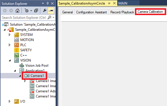
To run this sample, first open the project with the camera created and then open the calibration assistant for the camera instance.
Step 1 - Image acquisition
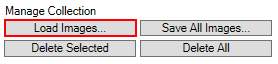
First, images of the calibration pattern taken by the camera to be calibrated must be loaded into the Assistant. This can be done either by direct image acquisition with the camera or by loading existing images. For this sample, you will find four suitable images ImgCalibAsymCirclesx.bmp of an asymmetrical circle pattern in the corresponding image folder. Load these images into the Calibration Assistant via Load Images....
Step 2 - Define asymmetric circle pattern
In this sample an asymmetric circle pattern is used as calibration pattern. In order to use one of the other pattern types, observe the respective definition:
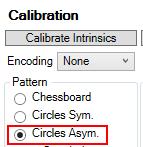
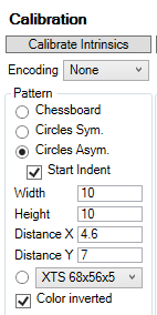
The asymmetric circle pattern must be selected in the Calibration Assistant for the loaded sample images:
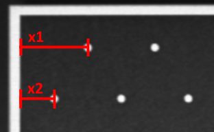
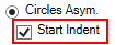
Due to the asymmetry, either the first (x1) or the second (x2) row of the circle pattern is indented. In this case the first (x1) row is indented, so Start Indent should be selected.
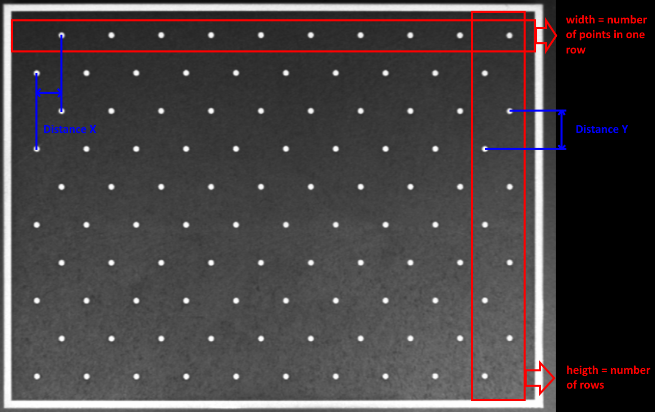
The width of the Width pattern corresponds to the number of points/circles in a row, while the Height corresponds to the number of rows. Distance X is used to specify the shortest distance between two circles in X direction. In the asymmetrical pattern, this is the distance to the next circle in the row below / above. Note the marking in the image. The distance between two rows is specified in Distance Y.
The Assistant expects black circles on white background. Since this example uses a pattern of white circles on a black background, the color must be inverted by selecting Color inverted.
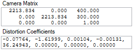
Step 3 - Calculate intrinsic parameters
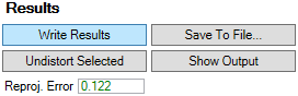
Once the calibration pattern has been fully defined, the intrinsic parameters can be calculated using the Calibrate Intrinsics button. The Reproj. Error should then be between 0 and 1, and the camera matrix and the distortion coefficients should be determined.
If this is not the case, the tooltip for the Reproj. Error provides information about the possible error. In addition, an image series is created under C:\ProgramData\Beckhoff\Vision\_CalibrationAssistantOutput that provides further information on the recognition of the pattern. Write access for the directory is required.
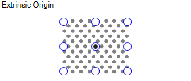
Step 4 - Calculate extrinsic parameters
After the intrinsic parameters the extrinsic parameters can be calculated. Only one image is used for this purpose, namely the image where the pattern is located in the plane on which the components are later measured, for example. This is the first of the sample images. Therefore, click on the first loaded image so that it appears in the image preview.
The zero point of the Extrinsic Orgin pattern can also be specified. By default, this is in the center of the pattern.
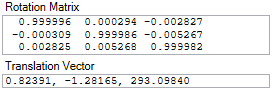
The Calibrate Extrinsics button then calculates the rotation matrix and the translation vector. The results can be found under Results.
Step 5 - Write results to the image provider of the camera
If the calibration was successful, the results can be written to the Image Provider of the camera via Write Results. This step is necessary so that the FB_VN_GevCameraControl camera function block in the PLC can access the calibration results.
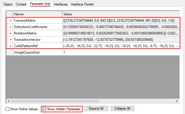
In the Image Provider, the calibration results can be found under Parameters (Init) if Show Hidden Parameters is selected.
After this step, make sure to activate the configuration by clicking on  . Otherwise the calibration results are not available in the PLC.
Step 6 - Load calibration results into the PLC
The FB_VN_GevCameraControl function block can be used to load the calibration parameters into the PLC:
Variables
hr                        :   HRESULT;
fbCamera                  :   FB_VN_GevCameraControl;
aCameraMatrix             :   TcVnMatrix3x3_LREAL;
aDistortionCoefficients   :   TcVnArray8_LREAL;
aRotationMatrix           :   TcVnMatrix3x3_LREAL;
aTranslationVector        :   TcVnVector3_LREAL;
Code
hr := fbCamera.GetCameraMatrix(aCameraMatrix);
hr := fbCamera.GetDistortionCoefficients(aDistortionCoefficients);
hr := fbCamera.GetRotationMatrix(aRotationMatrix);
hr := fbCamera.GetTranslationVector(aTranslationVector);
Step 7 - Transform pixels into world coordinates
Then use the F_VN_TransformCoordinatesImageToWorld_Points function to determine the coordinates of a point in the image in the real world in relation to the zero point of the calibration pattern, for example:
Variables
aPointImage               :   TcVnPoint2_LREAL;
aPointWorld               :   TcVnPoint3_LREAL
Code
hr := F_VN_TransformCoordinatesImageToWorld_Point(
        aSrcPoint                 :=  aPointImage,
        aDestPoint                :=  aPointWorld,
        aCameraMatrix             :=  aCameraMatrix,
        aDistortionCoefficients   :=  aDistortionCoefficients,
        aRotationMatrix           :=  aRotationMatrix,
        aTranslationVector        :=  aTranslationVector,
        fZ                        :=  0,
        hrPrev                    :=  hr);
Step 8 - Transform world points into image coordinates.
This transformation can be reversed with the F_VN_TransformCoordinatesWorldToImage_Points function, so that points from the world coordinate system are transformed in such a way that they can be displayed at the correct position in the image. This is useful for displaying auxiliary lines for better orientation in the image. The following code shows the world coordinate system in the image.
Variables
i                         :   INT;
aLine                     :   TcVnVector4_DINT;
aCoordinatesWorld         :   ARRAY[0..4] OF TcVnPoint3_LREAL := [ [0,0,0], [50,0,0], [-50, 0, 0], [0, 50, 0], [0, -50, 0] ];
aCoordinatesImage         :   ARRAY[0..4] OF TcVnPoint2_REAL;
Code
FOR i:= 0 TO 4 DO
    hr := F_VN_TransformCoordinatesWorldToImage_Point(
            aSrcPoint                :=  aCoordinatesWorld[i],
            aDestPoint               :=  aCoordinatesImage[i],
            aCameraMatrix            :=  aCameraMatrix,
            aDistortionCoefficients  :=  aDistortionCoefficients,
            aRotationMatrix          :=  aRotationMatrix,
            aTranslationVector       :=  aTranslationVector,
            hrPrev                   :=  hr);

    IF i > 0 THEN
        aLine[0] := REAL_TO_DINT(aCoordinatesImage[0][0]);
        aLine[1] := REAL_TO_DINT(aCoordinatesImage[0][1]);
        aLine[2] := REAL_TO_DINT(aCoordinatesImage[i][0]);
        aLine[3] := REAL_TO_DINT(aCoordinatesImage[i][1]);
    hr := F_VN_DrawLine_TcVnVector4_DINT(aLine , ipImageRes, aColorGreen, 3, hr);
    END_IF
END_FOR
Step 9 – View the results
When the program is executed, the playback of the camera stream must be started first. To do this, open the Record/Playback tab of the camera object, select the CameraSimulation.tcs file in the corresponding image folder and start the playback.
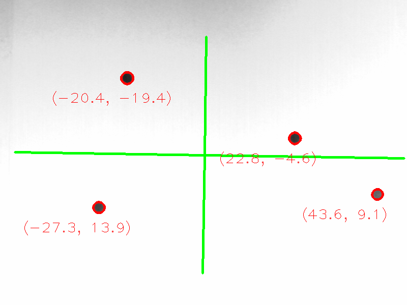
The resulting image can then be evaluated in the ADS Image Watch. One can see the drawn coordinate axes and the determined world coordinates of the individual points on the image.
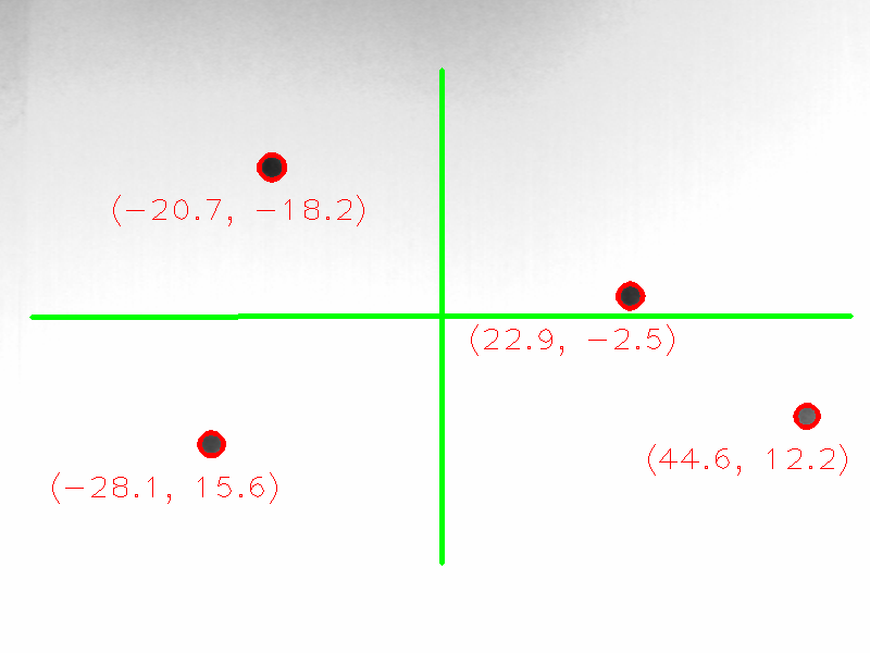
The result will be different if a different image or coordinate origin is used for the extrinsic calibration in step 4. The coordinate axes are shifted and the world coordinates of the pixels are also adjusted.