Move the axis in manual operation using Motion UI
Requirements
- An MC3 FluidPower axis was created, and its axis and encoder types were configured;
see Adding an axis. - The axis objects were linked to the hardware;
see Link axis objects to hardware. - The position measuring system has been configured;
see Set the position measuring system. - The valve output has been configured;
see Set the valve output.
Control signal limitation
- 1. Double-click the Position Controller object.
- 2. Open the Init Parameter tab.
- 3. Set the Velocity Feed Forward Factor = 1.0 in the General group.
- 4. Disable the position controller by setting all Control parameters = 0.0 in the Controller Parameters and Output Limitation groups.
- 5. Limit the control signal using the Minimum/Maximum Output to prevent uncontrolled, rapid movements.
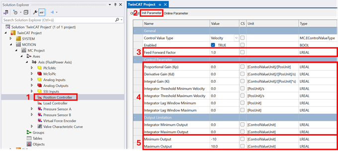
Select manual velocity
- 6. Double-click the Axis object.
- 7. Open the Init Parameter tab.
- 8. Reduce the Jog Velocity Slow setting in the Manual Motion group.
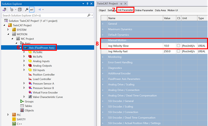
Move in manual operation
- 9. Click Motion UI.
- 10. Click Enable All to power the axis.
- 11. Move the axis by clicking on Jog Slow Positive / Negative.
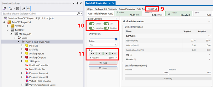
→ Check the counting direction of the position measurement system and the valve control based on the triggered movement.
→ If the position measurement system malfunctions, check the wiring or set the inversion (see Set the position measuring system). Repeat the check.
→ If the valve is malfunctioning, check the wiring or set the required inversion (see Set the valve output).
→ If the axis is drifting significantly, set a corrective offset for the output signal (see Set the valve output).
The next step is to identify the valve characteristics;
see Measuring the valve characteristics.