FB_AxisSync
This function block is used for synchronizing NC axes via a network ("distributed axes") and for avoiding associated beat effects. Internally the function blocks FB_TimeSync and FB_ExtrapolateAxisValues are used. These function blocks can also be used individually.
General
When NC axes are synchronized via a network, information from one axis (sender) is typically distributed cyclically to other axes (receivers) in the form of network variables. If the receivers are operated directly with the transferred information, beat effects caused by small phase differences in the real-time clocks become apparent. The beat effects manifest themselves as cyclic disturbance of the receiver axes, since information may be analyzed twice or skipped, depending on the phase difference. The frequency and duration of the disturbances depends on the phase difference and the jitter of the individual real-time clocks. Figure 1 shows the actual velocity of an axis operated directly via a network variable (position interface). The disturbances caused by beat effects due to step changes in the received set positions are clearly visible.
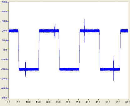
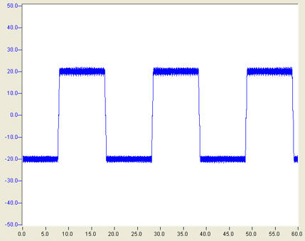
Figure 2 shows the actual velocity of an axis operated with values corrected through this function block. The previously observed disturbances have been corrected.
Description
The beat effects result from information being missed or read twice. These occurrences can be detected and countermeasures taken based on the cycle index, i.e. a counter that is incremented whenever network variables are sent. The function block is designed such that
a) the axis structures received as network variables and the corresponding cycle index are required as input for the block;
b) the axis information (set position and velocity) is corrected internally; and
c) an NC axis can be operated with the corrected information.
The cycle index and the cycle time(s) are transferred internally to the function block FB_TimeSync. This block determines the frequency of the beat and a correction time for extrapolating the kinematic axis information such that the beat effects are compensated. To this end the correction time is transferred to an instance of the function block FB_AxisExtrapolateValues, together with the received axis structure, which calculates the corrected set positions and velocities. Note that by default the set acceleration is used for correcting the position and the velocity. This feature must be deactivated in the event of non-smooth set acceleration, e.g. for encoder axes (stAxisSyncParameters.stAxisExtrapolateParameters.bUseAccForExtrapolation:=FALSE).The corrected set values are made available in the form of an axis structure and can then be used for operating the axis.
 | Critical Operating Notes Please ensure that the fcuntion block FB_AxisSync is called one time only in each plc cylce! |
VAR_INPUT
VAR_INPUT
    bEnable:              BOOL;
    iCycleIndex:          WORD;
    fTaskCycleTime:       LREAL;
    eFilterMode:          E_Sync_FilterMode;
    stAxisSyncParameters: ST_AxisSyncParameters;
END_VAR
bEnable : The FB is activated through a rising edge. If bEnable=FALSE, the input axis structure AxisIn is copied unmodified to output AxisOut.
iCycleIndex : Counter, which is incremented by 1 and transferred whenever axis structure AxisInis transferred. It is used for determining the beat frequency and for identifying fluctuations.
fTaskCycleTime : Zykluszeit [s].By default it is assumed that both sender and receiver are operated with cycle time fTaskCycleTime. In the event of different cycle times fTaskCycleTime corresponds to the receiver time, stAxisSyncParameters.stTimeSyncParameters.fDataCycleTime corresponds to the sender time.
eFilterMode :The method for calculating the corrected axis set values can be chosen irrespective of the state of the synchronization (displayed through via output bSynced). This does not affect automatic fallback (see ST_AxisSyncParameters.eFallBackMode), which is activated if the distance between the calculated and the original position exceeds a certain value. Automatic mode is activated by default, which means that
- a) The selected mode (ST_AxisSyncParameters.eStartUpMode) is used during initialization. Time mode is used by default, i.e. a cycle time is calculated in order to prevent fluctuations.
- b) As soon a sufficient number (stAxisSyncParameters.stTimeSyncParameters.iNoOfPeriodsForMeanDrift +1) of beat effects were detected, the system switches to sync mode, and the set values are extrapolated with the correction time.
- c) If synchronization is lost for some reason, the system switches to PT1 mode. In this mode the transferred positions are filtered before being transferred to the output.
stAxisSyncParameters : Structure for detailed configuration of the FB. The default values should be adequate in most cases.
VAR_OUTPUT
VAR_OUTPUT
    bSynced              : BOOL;
    bError               : BOOL;
    iErrorId             : DINT := 0;
    eFilterState         : E_Sync_FilterState;
    stAxisSyncDiagnostic : ST_AxisSyncDiagnostic;
END_VAR
bSynced : TRUE if the receiver is synchronized with the sender, otherwise FALSE.
bError : TRUE in the event of a fault
iErrorId : Provides the error code
eFilterState : Indicates what method was used for determining the set values returned in AxisOut. The following options are available:
- Bypass : The values supplied in AxisIn are transferred unmodified to AxisOut.
- PT1 : The input values were smoothed with the aid of a PT1 filter.
- Sync : The output values were determined from the input variables via the correction time.
- Time : The time correction is calculated such that any beat effects and fluctuations are compensated.
Further information can be found in the documentation for function block FB_TimeSync.
stAxisSyncDiagnostic : Diagnostic values
VAR_IN_OUT
VAR_IN_OUT
   AxisIn  : NCTOPLC_AXLESTRUCT;
   AxisOut : NCTOPLC_AXLESTRUCT;
END_VAR
AxisIn : Input axis structure of the sender.
AxisOut : Output axis structure with corrected axis set values.