FB_EL6821Communication
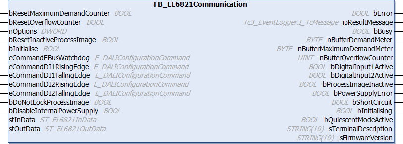
The function blocks for the DALI commands do not directly access the process image of the EL6821, but place the individual DALI commands in a command buffer. The function block FB_EL6821Communication sequentially reads the DALI commands from the command buffer and forwards them to the EL6821. This prevents multiple function blocks accessing the EL6821 process image at the same time.
The function block also reads the events of the DALI control devices from the EL6821 and stores them in a special table. The function blocks FB_DALIGetInputNotification and FB_DALIGetPowerCycleNotification are used to filter out the desired events from this table.
One instance of the function block FB_EL6821Communication must be created for each EL6821. This instance must be called in a separate, faster task. This faster communication task must have a higher priority than the task in which the function blocks for the individual DALI commands are called.
The utilization rate of the command buffer can be determined using the outputs of the function block. If you find that the command buffer is overflowing regularly, you should take the following steps:
- How heavily are the individual PLC tasks utilized? TwinCAT provides suitable analysis tools.
- Try to reduce the cycle time of the task in which the function block FB_EL6821Communication is called. The value should not be greater than 6 ms. The optimum value is 2 ms or less.
- If possible avoid polling (regular reading) of values. Only read values when they are actually required.
- Distribute the individual DALI devices evenly over several DALI lines. Since several DALI lines are processed simultaneously in each PLC cycle, this increases the data throughput.
For more information, see the chapter Bus Timing.
 Inputs
VAR_INPUT
  bResetMaximumDemandCounter : BOOL;
  bResetOverflowCounter      : BOOL;
  nOptions                   : DWORD := 0;
  bResetInactiveProcessImage : BOOL;
  bInitialise                : BOOL := FALSE;
  eCommandEBusWatchdog       : E_DALIConfigurationCommand := E_DALIConfigurationCommand.DoNothing;
  eCommandDI1RisingEdge      : E_DALIConfigurationCommand := E_DALIConfigurationCommand.Off;
  eCommandDI1FallingEdge     : E_DALIConfigurationCommand := E_DALIConfigurationCommand.DoNothing;
  eCommandDI2RisingEdge      : E_DALIConfigurationCommand := E_DALIConfigurationCommand.RecallMaxLevel;
  eCommandDI2FallingEdge     : E_DALIConfigurationCommand := E_DALIConfigurationCommand.DoNothing;
  bDoNotLockProcessImage     : BOOL := FALSE;
  bDisableInternalPowerSupply: BOOL := FALSE;
END_VAR
Name | Type | Description |
|---|---|---|
bResetMaximumDemandCounter | BOOL | A positive edge resets the stored value for the maximum utilization of the command buffer, nBufferMaximumDemandMeter (0…100 %). |
bResetOverflowCounter | BOOL | A positive edge resets the stored value for the number of overflows of the command buffer, nBufferOverflowCounter. |
nOptions | DWORD | Reserved for future extensions. |
bResetInactiveProcessImage | BOOL | A positive edge cancels the blocking of the process image of the terminal. The output bProcessImageInactive is reset to FALSE. The blocking is activated as soon as one of the two digital inputs on the terminal has been actuated and the input parameter bDoNotLockProcessImage is FALSE. |
bInitialise | BOOL | Configuration of the bus terminal is started by a positive edge at this input. Initialization is also carried out automatically when the controller is started. During this time no DALI commands are processed. |
eCommandEBusWatchdog | E_DALIConfigurationCommand | Defines the DALI command that is sent as soon as the bus terminal is no longer addressed via the E-bus. The value is written to the terminal by a positive edge at input bInitialise and stored there persistently. |
eCommandDI1RisingEdge, eCommandDI2RisingEdge | E_DALIConfigurationCommand | Defines the DALI command that is sent as soon as a rising edge is detected at the respective input of the bus terminal. The value is written to the terminal by a positive edge at input bInitialise and stored there persistently. |
eCommandDI1FallingEdge, eCommandDI2FallingEdge | E_DALIConfigurationCommand | Defines the DALI command that is sent as soon as a falling edge is detected at the respective input of the bus terminal. The value is written to the terminal by a positive edge at input bInitialise and stored there persistently. |
bDoNotLockProcessImage | BOOL | Defines whether the process image for the PLC is not blocked by actuating the digital inputs (see also bInactiveProcessImage). The value is written to the terminal by a positive edge at input bInitialise and stored there persistently. |
bDisableInternalPowerSupply | BOOL | Defines the operation mode of the internal DALI power supply unit. The value is written to the terminal by a positive edge at input bInitialise and stored there persistently. |
 Inputs/outputs
VAR_IN_OUT
  stInData                : ST_EL6821InData;
  stOutData               : ST_KL6821OutData;
END_VAR
Name | Type | Description |
|---|---|---|
stInData | Structure in the input process image of the EL6821. It is used for communication from the EL6821 to the PLC. | |
stOutData | Structure in the output process image of the EL6821. It is used for communication from the PLC to the EL6821. |
 Outputs
VAR_OUTPUT
  bError                    : BOOL;
  ipResultMessage           : I_TcMessage;
  bBusy                     : BOOL;
  nBufferDemandMeter        : BYTE;
  nBufferMaximumDemandMeter : BYTE;
  nBufferOverflowCounter    : UINT;
  bDigitalInputnActive      : BOOL;
  bProcessImageInactive     : BOOL;
  bCollisionError           : BOOL;
  bPowerSupplyError         : BOOL;
  bShortCircuit             : BOOL;
  bInitialising             : BOOL;
  bQuiescentModeActive      : BOOL;
  sTerminalDescription      : STRING(10);
  sFirmwareVersion          : STRING(10);
END_VAR
Name | Type | Description |
|---|---|---|
bError | BOOL | This output is switched to TRUE if an error occurs during the execution. Further information about the error can be queried via the variable ipResultMessage. |
ipResultMessage | I_TcMessage | Interface pointer (see error evaluation) that can be used to obtain detailed information about the processing of the function block (see runtime messages). |
bBusy | BOOL | The output is set as soon as execution of the DALI commands has commenced. It remains active until all DALI commands have been processed. |
nBufferDemandMeter | BYTE | Utilization rate of the command buffer (0…100 %). |
nBufferMaximumDemandMeter | BYTE | Maximum utilization rate of the command buffer reached so far (0…100 %). The counter can be reset via the input bResetMaximumDemandCounter. |
nBufferOverflowCounter | UINT | Number of command buffer overflows to date. The counter can be reset via the input bResetOverflowCounter. |
bDigitalInput1Active, bDigitalInput2Active | BOOL | One of the digital inputs at the terminal was actuated or is actuated (see also terminal documentation). If the input bDoNotLockProcessImage is not set, the output bProcessImageInactive is set and no further DALI commands can be sent via the bus terminal. |
bProcessImageInactive | BOOL | One of the two digital inputs on the bus terminal was actuated and bDoNotLockProcessImage is initialized with FALSE. No further DALI commands can be sent from the PLC via the bus terminal. The blockage can be released again via the input bResetInactiveProcessImage. |
bCollisionError | BOOL | A data collision was detected on the DALI bus while a DALI command was sent. |
bPowerSupplyError | BOOL | When using the internal DALI power supply unit: Power supply unit fault detected. |
bShortCircuit | BOOL | The 24 V DC supply voltage at connections 1 and 5 of the EL6821 is missing, or a short circuit has been detected on the DALI bus. |
bInitialising | BOOL | During initialization of the bus terminal, the output is set and remains active until initialization has been completed. Initialization is also carried out automatically when the controller is started. During this time no DALI commands are processed. |
bQuiescentModeActive | BOOL | If the EL6821 receives the DALI command START QUIESCENT MODE, this output is set to TRUE. This tells the PLC program that the Quiescent mode is active. This remains active for approx. 15 min or until the DALI command STOP QUIESCENT MODE has been received. |
sTerminalDescription | STRING | Contains the Terminal Name (e.g. EL6821). This information is contained in CoE object 16#1008 of the bus terminal. |
sFirmwareVersion | STRING | Contains the firmware version. This information is contained in CoE object 16#100A of the bus terminal. |
 Properties
Name | Type | Access | Initial value | Description |
|---|---|---|---|---|
nInvalidFrameCounter | UDINT | Get | 0 | Counter for the invalid data frames received by the terminal. If a valid data frame is received, the counter is reset. |
Requirements
Development environment | Required PLC library |
|---|---|
TwinCAT from v3.1.4024.47 | Tc3_DALI from v3.16.1.0 |