Command Properties (object)
Function: The command enables the Properties view, which displays general information about the currently selected object.
Call: Context menu PLC object
Requirement: An object in the PLC project tree is selected.
Depending on the object currently selected, the following property areas are displayed:
- Advanced (compile settings)
- Image
- Licenses
- General (object name, object path)
- SFC Settings (flags for Sequential Function Chart)
- CFC settings (Execution order mode)
 | The special visualization properties are documented under Visualization object and the special library and placeholder properties are documented under Command Properties. |
Advanced
This area shows the settings for compiling the object.
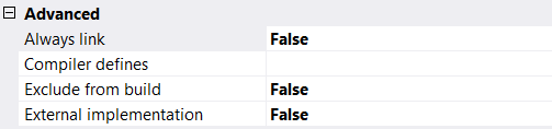
Always bind | True: The object is selected in the compiler and therefore always included in the compile information. It is therefore always compiled and loaded onto the PLC. This option becomes relevant if the object is located below an application or referenced via libraries that are also located below an application. The compile information is also used as a basis for the selectable variables of the symbol configuration. Alternatively, the {attribute 'linkalways'} pragma can be used to instruct the compiler to always include an object. |
Compiler definitions | The compiler definitions entered here are not evaluated. If you want to use compiler definitions, enter them in the PLC project properties. See:
|
Exclude from compilation | True: The object is not included in the next compilation run. |
External implementation | (Late binding in the runtime system) The use of this functionality is only possible in special constellations. As a rule, you can ignore this option. True: No code is generated for this object when the project is compiled. The object is not linked until the project is loaded to the target system, provided it exists there (in the PLC runtime system or in another real-time module). |
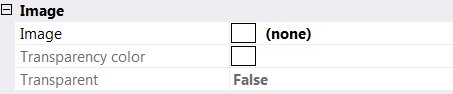
Image
In this area you can assign an image to the object, which is displayed in the graphical view of the library manager and in the toolbox of the FBD/LD/IL editor. Transparency of the image can be achieved by selecting a color, which is then displayed transparently. If you select the option Transparency Color, you can use the rectangular button to the right of it to open the standard dialog for selecting a color.
Licenses
This section contains a list of licenses for the object.

General
In this section you will find general information about the selected object.
FileName | File/object name |
FullPath | Storage path/location of the object (not editable at this point) |
Version | File version, values:
(not editable at this point, indirectly configurable via the storage format, see Format property) |
| Engineering incompatibility of file version 1.2.0.0 (or higher) with TwinCAT 3.1 < build 4024 Please note that objects saved with file version 1.2.0.0 (or higher) cannot be loaded with Engineering versions lower than TwinCAT 3.1.4024! Since an object is automatically saved with file version 1.2.0.0 when using the optional Base64 format, objects with Base64 format cannot be loaded with Engineering versions lower than TwinCAT 3.1.4024. If a PLC project contains objects with the file version 1.1.0.1 and objects with the file version 1.2.0.0, the 1.1.0.1 objects are loaded with an Engineering version lower than TwinCAT 3.1.4024. Objects with file version 1.2.0.0 are not loaded. The file version of a file saved with file version 1.2.0.0 can be reset to 1.1.0.1 using XAE version TwinCAT 3.1.4024 or higher. |
Options
In this section you will find some options that can be configured for PLC objects.
Format | Individual setting option of the storage format: The storage format of an object can be individually configured at this point for the object types listed below. Storage format, values:
Advantages of Base64 over XML: Base64 results in compressed storage, compared to XML. As a result, improved performance can be achieved with file access to these objects, which can be used, for example, when loading, moving or copying objects. Availability of Base64: The Base64 storage format is optionally available from build 4024 for the following PLC objects:
Setting option for the standard storage format: For a PLC project, the setting "Write object content as" in the PLC project properties (Category Advanced) can be used to define the standard storage format for the object types mentioned above. |
Separate LineIds | Value: True or False
(not editable at this point, configurable in the Write options) |
Sort | Value: Name or GUID Specifies the sequence in which the child objects (such as methods) are stored in the parent object: either sorted by name or by GUID. (not editable at this point, configurable in the Write options) |
Write ProductVersion | Value: True or False (not editable at this point, configurable via the setting "Write product version in files" in the Category Advanced of the PLC project properties) |
SFC settings
This area displays the current settings for compiling and handling implicit variables for the currently selected SFC object.
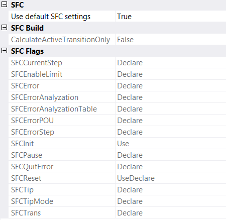
Use default SFC settings | True (default): With this option, the default values defined in the PLC project properties can be applied to the currently selected object and displayed in the Properties view of the object. False: This option allows you to configure SFC settings that are valid specifically for this SFC object. |
Calculate active transitions only | True (default): TwinCAT only generates code for transitions that are currently active. This setting can significantly reduce the runtime of the SFC diagram compared to the deactivated option. False: TwinCAT generates code for all transitions. The states of all transitions are displayed online in color (True in dark blue, False in light blue). |
SFC flags | Implicitly generated variables (Flags) for controlling and monitoring the processing in an SFC diagram. Use: The corresponding variable is used. Declare: The corresponding variable is created automatically. UseDeclare: The variable is created and used. |
CFC settings
| Available from TwinCAT 3.1 Build 4026 |
This area sets the execution order mode for the selected CFC object. In the CFC editor, you freely position the elements and thus the networks. To avoid that the execution order in the CFC programming block is undefined, two modes are available.
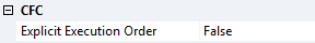
Explicit Execution Order | False (default): Automatic data flow mode True: Explicit execution order mode |
Automatic data flow mode
In this mode, the execution order is automatically set according to data flow and, in case of ambiguity, according to network topology. The programming blocks and the outputs are numbered internally. The upper networks are executed before the lower networks and the left networks before the right networks.
Advantage: The automatically defined execution order is time and cycle optimized. You do not need any information about the internally managed execution order even during the development process.
The elements in the CFC editor are displayed without marks and without numbering. It is not possible to change the execution order manually. For networks with feedback, you can additionally set a starting point.
In the menu CFC > Execution order the following commands are available in this mode:
Explicit execution order mode
In this mode you can explicitly set the execution order. For this purpose, the elements are displayed in the CFC editor with marks and numbering, and menu commands are provided that allow you to determine the order.
The following commands are available in the menu CFC > Execution order:
- Command Move to Beginning
- Command Move to End
- Command Forward by one
- Command Back by one
- Command Set Execution Order
- Command Order by Data Flow
- Command Order By Topology
| Until build 4026, this was the usual behavior of CFC programming blocks. Note that you must adjust the execution order on your own responsibility and judge the consequences and effects yourself. For this purpose, the execution order is constantly displayed. |