Workpiece measurement (Index 0x7000:07)
Workpieces or the distances between workpieces can be measured, calculated and evaluated with the aid of the function Workpiece measurement.
A 32-bit filter value [Number of increments] can be defined in “Latch filter value” (index 0x8000:1B) for reliable distinction between a signal relevant for the measurement and production-related signal interference.
Six different modes are available for the measurement. The measurement mode is defined in “Measurement mode” (index 0x8000:1C).
Measurement sequence
The workpiece measurement function is activated by setting the “Enable measurement” bit (index 0x7000:07) to TRUE.
 | No simultaneous activation of the functions Workpiece measurement and Compare function The simultaneous activation of the functions Workpiece measurement (“Enable measurement” index 0x7000:07) and Compare function (“Enable output functions” index 0x7000:06) is not possible. |
The sequence of measurement for the different measurement modes is described below.
- Measurement modes 0 + 1 - HIGH-level and LOW-level are detected
- The measurement begins with a HIGH-level at the external latch. The initial value is written into “Latch value, rising edge” (index 0x6000:17) on expiry of the filter value. If a high level is already present, the initial value of the counter is written into “Latch value, rising edge” (index 0x6000:17).
- The measurement ends with a LOW-level at the external latch. The counter value is written into “Latch value, falling edge” (index 0x6000:18) on expiry of the filter value.
- The end of the measurement is acknowledged with the setting of the bit in “Measurement done” (index 0x6001:02).
- Measurement modes 2 + 3 - Only HIGH-level is detected
- The measurement begins with a HIGH-level at the external latch. The initial value is written into “Latch value, rising edge” (index 0x6000:17) on expiry of the filter value.
- The end of the measurement is acknowledged with the setting of the bit in “Measurement done” (index 0x6001:02).
- Measurement modes 4 + 5 - Only LOW-level is detected
For the time, see following Fig. | HIGH- and LOW-level are detected Measurement mode: | HIGH-level is detected Measurement mode: | LOW-level is detected Measurement mode: |
|---|---|---|---|
t1 | Start of the measurement, | Start of the measurement, | - |
t2 | The counter value from t1 is written into “Latch value, rising edge” (index 0x6000:17). | The counter value from t1 is written into “Latch value, rising edge” (index 0x6000:17). | - |
t3 | Start of the filter | - | Start of the measurement, |
t4 | The counter value from t3 is written into “Latch value, falling edge” (index 0x6000:18). | - | The counter value from t3 is written into “Latch value, falling edge” (index 0x6000:18). |
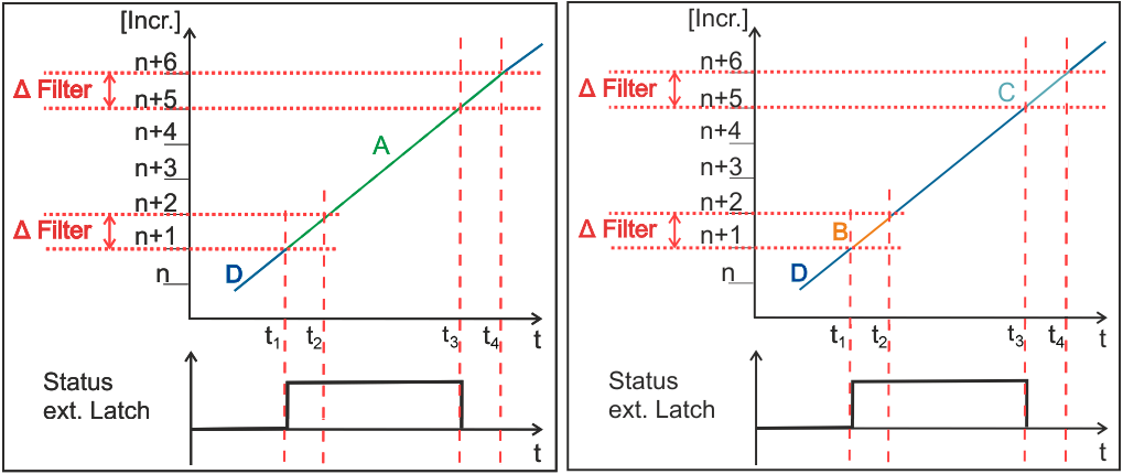 Fig.155: Graphical illustration of the measurement
Left | Right |
Sequence in case of signal interference (fig. Graphical illustration of measurement in Mode 0 - signal interference)
t1: The measurement begins with a positive edge. The counter value is buffered.
t2: A new edge change takes place within the filter interval; the buffered value is discarded.
t3: When the next corresponding edge arrives, the new value is buffered.
t4: On expiry of the filter interval the counter value buffered at the time t3 is written into “Latch value, rising edge” (index 0x6000:17).
t5: The counter value is buffered on a falling edge.
t6: On expiry of the filter value the counter value buffered at the time t5 is written into “Latch value, falling edge” (index 0x6000:18).
The bit in Measurement done (index 0x6001:02) is set to TRUE.
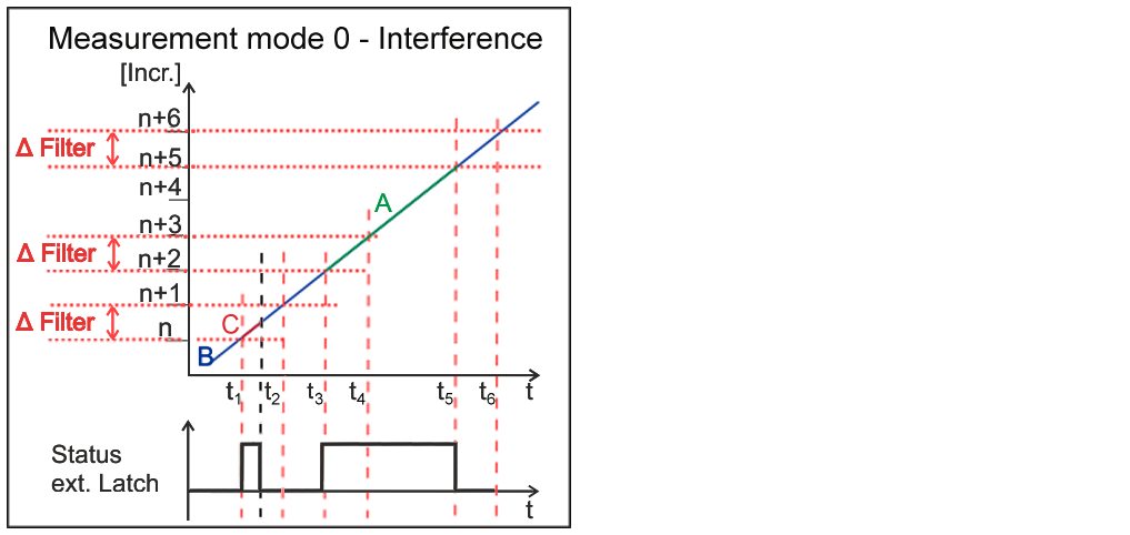 Fig.156: Graphical illustration of measurement in Mode 0 - signal interference
A: Measurement valid, B: Measurement inactive, C: Measurement invalid