Basic function principles
Operating modes of the EL2522
In addition to the "enhanced operating mode" known from the EL2521, the EL2522 also supports an "enhanced operating mode with continuous position specification" and an "enhanced operating mode with continuous position specification and arrival time".
As an extension to the EL2521, the EL2522 offers the "enhanced operating mode" in single-channel or single operating mode with A-, B- and C-track (zero track / reference) or in 2-channel or double operating mode, each with A- and B-track.
Version | PDO settings | Comments | ESI | Process data | CoE parameters | |
|---|---|---|---|---|---|---|
Legacy | formerly MDP 252 | not available for the EL2522 | - | - | - | - |
enhanced operating mode | 1 Ch. Standard 16 Bit (MDP 253/511) 2 Ch. Standard 16 Bit (MDP 253/511) 1 Ch. Standard 32 Bit (MDP 253/511) 2 Ch. Standard 32 Bit (MDP 253/511) | 1 Ch.: with C-track | from 02 | from EL2522-0000 | PDO Assignment Inputs: 0x1A00, 0x1A02 Outputs: 0x1600, 0x1602, 0x160A | Feature bits and settings in CoE objects (hex) 8000, 8010, 8020 and 8030 |
enhanced operating mode with continuous position specification | 1 Ch. Standard 32 Bit (MDP 253/511), continues position 2 Ch. Standard 32 Bit (MDP 253/511), continues position | 1 Ch.: with C-track; path without ramp, DC-Synchronous must be selected | from 02 | from EL2522-0000 | PDO Assignment Inputs: 0x1A03 | |
enhanced operating mode with continuous position specification and arrival time | 1 Ch. Standard 32 Bit (MDP 253/511), 2 Ch. Standard 32 Bit (MDP 253/511), | 1 Ch.: with C-track; path without ramp, specification of arrival time possible (target time); DC-Synchronous must be selected | from 02 | from EL2522-0000 | PDO Assignment Inputs: 0x1A03 |
Output modes of the EL2522
The EL2522 has three different output modes. A choice can be made via index 0x8000:0E for incremental encoder 1 or index 0x8010:0E for incremental encoder 2 between the output modes:
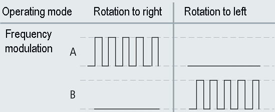
- "Frequency modulation (value: 0)",
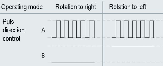
- "Pulse direction specification (value: 1)" and
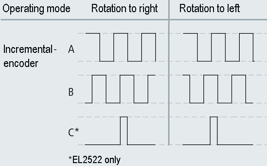
- "Incremental encoder (value: 2)".
In addition, the EL2522 operates cycle-synchronously when using the "continuous position" PDO presets and thus generates pinpoint output control clock signals synchronously with the task cycle.
With the additional selection "continuous position w. arrival time", a target time in which a target position is to be reached is specified instead of a frequency. The clock signals are also output cycle-synchronously in this case, too, as long as this specification is within the plausible range.
Output modes | Meaning | Index 0x8000:0E value |
|
|---|---|---|---|
Frequency | Only one channel is active per direction, on which a frequency-modulated signal is output. | 0 |
|
Pulse | The direction is controlled by channel B. The clockwise direction is represented by a low level and the counter clockwise direction by a high level. The actual signal, conversely, is output in modulated form via channel A. | 1 |
|
Incremental | The direction is defined by the shifting of channels A and B. If channel A leads by 90°, this indicates a "forward" movement. If channel B leads by 90°, this indicates a "reverse" movement. | 2 |
|
 | Process data monitoring
|
Delivery state
Independent of the hardware/firmware version, an EL2522 newly integrated in the system registers itself in the operating mode "2-channel standard 32-bit (MDP 253/511)".
Enhanced operating mode: Incremental encoder simulation
The "enhanced operating mode (253/511)" is the enhanced operating mode familiar from the EL2521. Please refer to the corresponding chapter of the EL2521 (see also chapter EL2521 function) for an explanation of the functionality and the steps necessary for commissioning.
Unlike the EL2521, it is possible to choose between a 1-channel and a 2-channel operating mode (single or double operation).
- In 1-channel operating mode a C-track is output in addition to the A- and B-tracks.
- In 2-channel operating mode two outputs are offered per channel, each with an A- and a B-track. Both behave in the same way as the known 1-channel operating mode.
Enhanced operating mode: Incremental encoder simulation with continuous position specification.
In the operating modes 1-channel standard 32-bit, continuous position, and 2-channel standard 32-bit, continuous position, the EL2522 can simulate an incremental encoder with A-, B- and C-tracks (1-channel or single operating mode) or two independent incremental encoders (2-channel or double operating mode), each with an A- and a B-track. As previously with the EL2521 there is also a choice here between the output modes incremental encoder, frequency modulation or pulse direction control.
Basically, the clock signals are output here cycle-synchronously (necessary selection in the EL2522 DC settings: DC-synchronous).
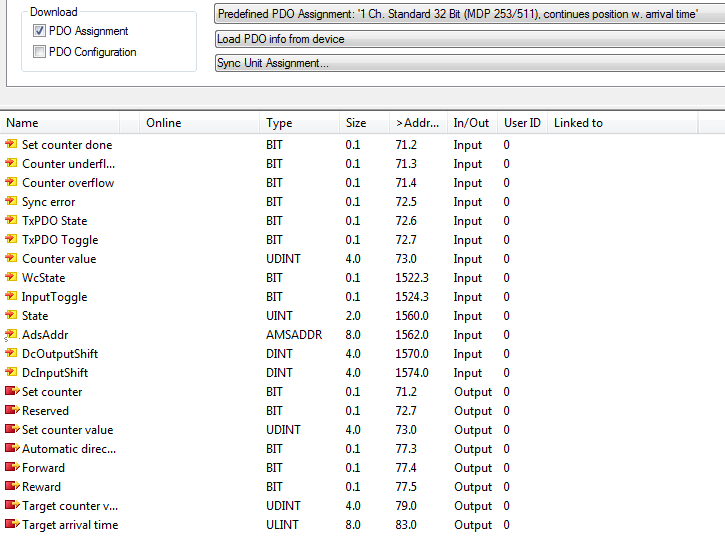
After selection of the respective PDO assignment, the associated process data are represented in accordance with the following illustration.
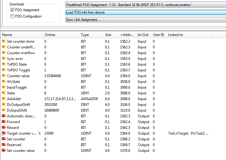
The output value "Target counter value" is written with the desired target position for the next cycle. Depending on the current position (input value "Counter Value"), the EL2522 calculates the frequency necessary for reaching the desired position in the next cycle. A fixed running direction can be specified by the output bits "Forward" and "Reverse". If the "Automatic direction" bit is set, the terminal selects the running direction depending on the position difference (actual and target value) in favor of the shorter distance.
If 2-channel mode is in use, the process data for the second incremental encoder are added analogously to those for the first.
Enhanced operating mode: Incremental encoder simulation with continuous position specification and arrival time
In addition to the functions mentioned above, it is possible in the operating mode "continuous position specification and arrival time" to define when the target position should be reached. Consequently, the calculation no longer takes place with the specification of the target position to be reached in the next cycle, but taking into account an arrival time specified by the user instead.
The desired target time for reaching the target position can be specified by the output value "Target Arrival Time". The frequency is then calculated accordingly. If the calculated frequency should be higher than the set maximum frequency ("Base Frequency 1": incremental encoder 1: index 0x8000:12 or incremental encoder 2: index 0x8010:12), then the frequency is limited to this value and the target position is accordingly reached at a later time.
| Use of micro-increments When using micro-increments, care must be taken that the internal 100 MHz is not exceeded. Example: |
| Setting the counter value / zero calibration (A/B adaptation) The counter value can be manually set. To do this, the desired counter value must be entered in the index 0x7020:11 (Set counter Value). If index 0x7020:03 (Set Counter) is now set, the counter value is adopted. At the same time, the parameters for the running direction must be set to FALSE (Automatic Direction, Forward, Backward, 0x7000:04 – 0x7000:06). If the counter value is set to "0", the C-track goes into the "high" state.
|
Function: automatic adoption of the target value
In the enhanced operating modes "continuous position specification" and "continuous position specification with arrival time" a threshold value (object 0x8020:1A for incremental encoder 1, object 0x8030:1A for incremental encoder 2) can be specified for the automatic adoption of setpoints. If the difference between the setpoint and the actual value exceeds this preset threshold value, the actual value will be overwritten with the setpoint on the next Sync; i.e. the value of the target counter is directly adopted as the counter value WITHOUT incremental encoder clock signals being output.
→ The following steps must be performed in order to use this function.
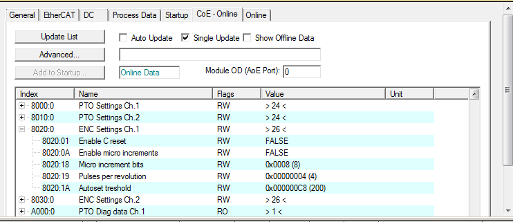
Example:
- 0x8020:1A = "Autoset treshold" = 0x00000100
- (→ the value is >=1: Autoset Threshold, "Automatic setting" is activated)
- Cycle n (setting the target counter value):
- "Target counter value" = 0x00000200
- "Counter value" = 0x00000000
→ threshold for automatic setting is exceeded; NO clock signals will be output at the output of the terminal.
- The "Target counter Value" is directly adopted into the "Counter value".
- "Target counter value" = 0x00000200
- "Counter value" = 0x00000200
- Cycle n+1 (resetting the target counter value):
- "Target counter value" = 0x00000220
- "Counter value" = 0x00000200
The threshold (0x00000100) is NOT overwritten with the difference between target counter value and current counter value (in this case the value: 0x20) for automatic setting. Therefore clock signals are output at the output of the terminal until the target counter value is reached.
- Cycle n+2 (continuation in this operation mode with further target counter values):
- "Target counter value" = 0x????????
- "Counter value" = 0x00000220
This function accordingly enables the counter value to be set directly as an alternative to using the object 0x7020:03 (or 0x7030:03) "Set counter".
It is recommended to use the function of the automatic adoption of the setpoint only in special exceptional cases!
| Initialization The actual value is initialized during the transition from SafeOp to Op. The current setpoint is adopted here as the actual value. |
| Exceeding the maximum frequency If the set maximum frequency is exceeded when calculating the necessary frequency for reaching the target position within the foreseen period, the maximum frequency is adopted. This leads to "extended" travel distances and should be taken into account and if necessary checked accordingly. The maximum frequency can be set via index 0x8010:12 / 0x8020:12 (Base Frequency 1). |