Configuration of an axis
In contrast to the Beckhoff NC, the axis in the hydraulic library is configured by the application itself. This means that the function blocks for operating an axis (read actual value, generate setpoints, generate position rules, linearization and output) must be called up individually.
All function blocks work on a common axis reference, which must be created globally. If there is more than one axis, the axis references must be created as an array.
In addition to the axis reference (AXIS_REF_BkPlcMc), the I/O structures ST_TcPlcDeviceInput and ST_TcPlcDeviceOutput must be declared for each axis. Further optional elements are added, depending on the application.
To view messages a ST_TcPlcMcLogBuffer should be declared. This buffer is shared by all axes.
If other sensors such as pressure or load cells are used in the application in addition to position detection, the I/O value must be set in the application. The parameterization of the scaling can be managed in the fCustomerData[] section of the axis. For each axis 20 customer-specific data are provided in this section. This data is saved via the axis, loaded and displayed in the PLcMcManager. For the display in the PlcMcManager the label can be changed by declaring the structure ST_TcMcAuxDataLabels.
Sample for the data of an axis
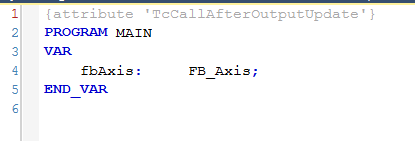
General settings
An attribute must be set in TwinCAT 3 so that the I/O is always read in with a constant time interval, regardless of the time required by the program.
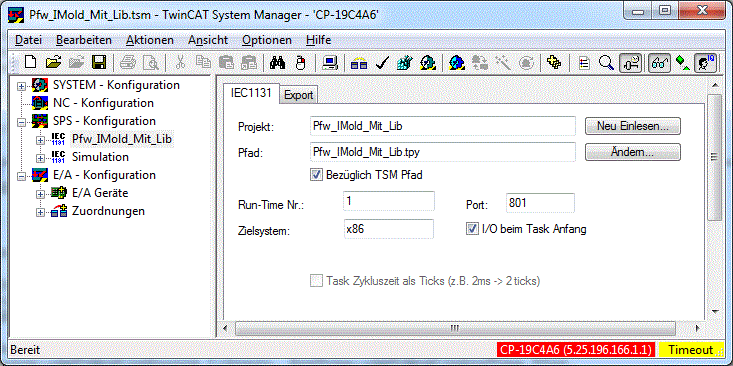
In TwinCAT 2, the I/O flag at the start of the task must be set in the System Manager under PLC configuration.
In contrast to NC, the hydraulic axis itself (setpoint generator, controller, etc.) is calculated directly in the PLC. It is therefore recommended to set the cycle time of the task to less than 10 ms.
Initialization
The PLCopen standard specifies that all Motion function blocks of the application are called with an instance of type AXIS_REF_BkPlcMc. For technical reasons, some axis components cannot be contained in such an instance, since they must be located in separate areas (e.g. process images). Other elements are optional and are only be added if required. To link them to the axis reference, they are transferred to an initialization function block of type MC_AxUtiStandardInit_BkPlcMc.
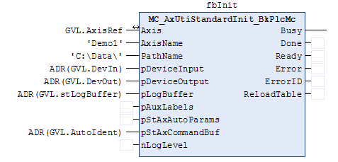
When called for the first time, the function block links the input and output structures and all optional elements with the axis reference. Variables that have to be passed as addresses are marked with the prefix "p". The function block should be called cyclically to check the pointer addresses.
 | It is not permitted to bind an instance of ST_TcPlcDeviceInput, ST_TcPlcDeviceOutput or ST_TcMcAutoUdent to multiple axes. It is not permitted to connect more than one instance of ST_TcMcLogBuffer to axes. |
The function block loads the parameters from the given file path and transfers them to the axis reference. All parameters are stored in binary form in an Axis name.dat file.
Once the parameters have been loaded successfully, the bParamsEnable flag in the axis reference becomes TRUE. Only now is the use of parameters that have not yet been defined ruled out, and all other axis-related function blocks may be called.
Actual value acquisition
The encoder type set in the parameter structure of the axis reference determines how and from which variables of the input structure the MC_AxRtEncoder_BkPlcMc function block will read the actual value and convert it to a position [mm] and a velocity [mm/s]. The connection is monitored when EtherCAT components are used.
If the actual values are very noisy, it is possible to filter them via a sliding average value (MC_AxUtiSlidingAverage_BkPlcMc) or a Pt1 element (MC_AxUtiPT1_BkPlcMc). The use of custom filters is possible.
Filter function blocks must be called after the encoder function block. The variable to be filtered must be passed to their input. The result can be written back to the corresponding variable of the axis reference. This causes the old noisy value to be replaced by a new, stabilized value.
| If a heavily filtered actual value is used for control purposes, the dynamics and controllability can be affected due to the filter jump response. |
Additional function blocks are available for reading in pressure and force values. The function block to be used depends on the variable to be measured. In contrast to position determination, for force and pressure determination the mapping interface and terminal monitoring must be provided by the application.
| MC_AxRtHybridAxisActuals_BkPlcMc is an adapted function block for determining the essential actual values of a servo-electric/hydraulic hybrid axis. |
Setpoint generation and default position controller
If, for example, MC_MoveAbsolute_BkPlcMc triggers an active movement of the axis, the setpoint generator calculates the current values for the set velocity and the set position in each cycle. This can be done in a time-controlled or path-controlled manner. Permanent position control is required for time-controlled generation, otherwise this is only required at standstill. Several profile variants are supported. For more information, please refer to the documentation for the function block.

If the axis does not have a command buffer, a command is entered directly in the runtime data of the axis. Otherwise, commands are buffered, subjected to path planning, and then made effective according to the blending rules.
If required, the application can handle the setpoint generation. An MC_AxRtSetExtGenValues_BkPlcMc function block must be used for this purpose. If external generation is active, the library block to be called is switched to a passive state and then reactivated. In this way, application-specific gear units and other non-standard mechanisms can be realized.
The setpoint generator and a default position controller that is adequate in most cases are integrated in the MC_AxRuntime_BkPlcMc function block.
Alternative position controller
If another controller is called after the default position controller and fLagCtrlOutput is overwritten in the runtime data of the axis reference, another position controller can be activated. This can be a customer-specific controller or another controller from the library such as the FB MC_AxRtPosPiControllerEx_BkPlcMc.

This library controller is a PID controller with optional extensions such as condition feedback and acceleration pre-control.
Further controllers
Pressure or force controllers are used in many applications with hydraulic axes. As an example, an MC_AxCtrlPressure_BkPlcMc function block is shown here.

In the active state, the function block overwrites the output of the setpoint generator. In order for the controller response to take effect, it must be called up before linearization.
| When activating or deactivating, step changes in the control values of the axis can occur depending on the parameter values. |
Final processing
At this point, the control values of the axis are present in a form that assumes linear behavior of the axis and its components. In practice, this is rarely the case. To take this into account, the control values (setpoints, controller outputs, overlap compensation) are combined to an output value and subjected to linearization. This adjustment can be carried out in sections or based on characteristic curves.
Sectional linearization
The library provides the function block MC_AxRtFinish_BkPlcMc for simple linearization.

The set velocity weighted with the pre-control and the controller output are added to the output velocity.
An active overlap compensation is selected such that it is ramped linearly from zero to the set overlap compensation Ovl between 0 and VCreep. It is fully effective for the remaining area.
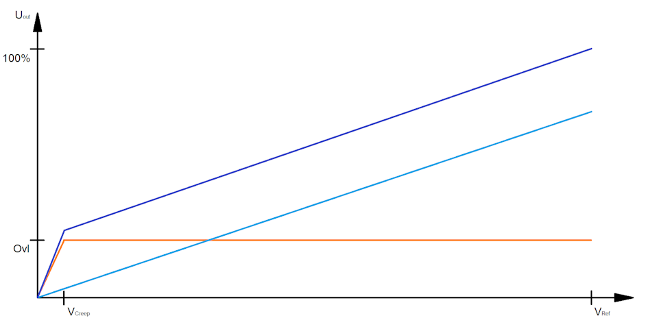
The direction dependency is compensated. The output velocity is multiplied by fAreaRatio from the axis parameters if the velocity is positive and fAreaRatio ≥ 1.0. If the velocity is negative and fAreaRatio ≤ 1.0 division is applied.
The output is formed by adding the weighted target velocity, the controller output, the active overlap compensation and the offset correction.
Linearization based on characteristic curve
The library provides the function block MC_AxRtFinishLinear_BkPlcMc for this linearization with higher resolution.
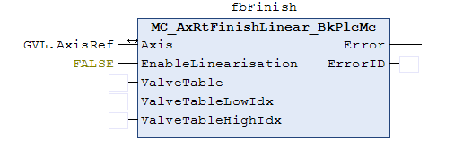
If the use of the characteristic curve is not enabled or not possible, an internal function block is used for sectional linearization. This is the case if at least one of the following reasons applies:
- FALSE is transferred at the enable input of the function block.
- No instance of type ST_TcMcAutoIdent has been linked to the axis reference.
- bLinTabAvailable in the axis parameters is FALSE: The characteristic curve is not valid.
Otherwise, the target velocity weighted with the pre-control and the controller output are added to the output velocity. The two characteristic curve points closest to the calculated value are determined and the output value is formed by intermediate interpolation and addition of the offset correction.
Characteristic curve measurement
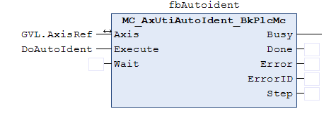
The function block MC_AxUtiAutoIdent_BkPlcMc supports the measurement of a characteristic curve by means of a standardized automatic sequence. The parameters to be set for this are stored in the structure ST_TcMcAutoIdent. If a characteristic curve measurement and a characteristic curve-based linearization are to be used, such an element must be created and connected to the axis reference.
| An MC_AxUtiAutoIdent_BkPlcMc function block must be called after the MC_AxRtFinishLinear_BkPlcMc function block and before the MC_AxRtDrive_BkPlcMc function block of the axis. |
The characteristic curve determined in this way combines the influences of a number of sources:
- Non-linearities of the valve
- Asymmetry of the cylinder
- Flow effects at higher velocities
- Possible limitations due to a pump
- Positional influences such as gravitation
- Influences of other components in the oil flow
| With a servo-electric/hydraulic hybrid axis, no MC_AxUtiAutoIdent_BkPlcMc function block may be activated. |
Output adjustment
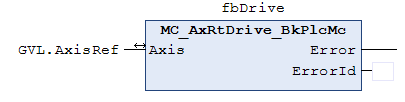
At this point, the control values for the axis are available as physical or standardized parameters. Only the MC_AxRtDrive_BkPlcMc function block determines an output parameter that represents these parameters in a form that is converted to the desired response by the device used. The method used and its parameters are set in the parameter structure of the axis reference.
Interfacing of the PlcMcManager
In preparation.
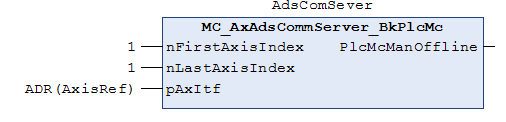
The PlcMcManager is connected via the TwinCAT ADS service. Since this allows only one port per application, all axes must use a common connection. Multiple instances of this function block are not permitted.
The sample shown applies to an application with only one axis. Multi-axis projects must combine the axis references in an array whose address and first and last index are transferred.
This FB must be called independently of whether axes can load their parameters.
Message logging
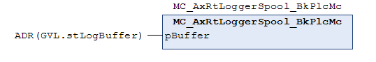
All axes of an application share a logging buffer. To send the messages that arrive there to the Event Log of the operating system and, if available, to the message window of the development environment, create an instance of the function block MC_AxRtLoggerSpool_BkPlcMc for each application. The call of the function block is independent of whether axes can load their parameters.