Example "Activating a Planar part position and moving a Planar mover"
In this example, a Planar mover is moved to three Planar parts while the movable one of the parts is moved.
Starting point
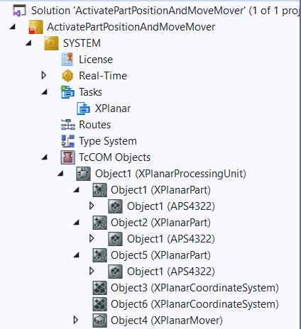
You start with a solution that contains a fully configured XPlanar Processing Unit. Three parts, two coordinate systems and a mover are created under the XPlanar Processing Unit. A tile is created under each of the three parts.
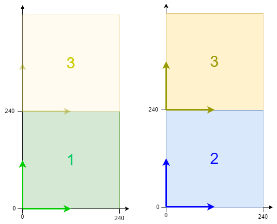
The following geometric situation is set: the first two parts are fixed in the two coordinate systems at the origin and the third part can change position between the two coordinate systems. It is conceivable, for example, that the two coordinate systems are arranged one above the other in two planes and Part 3 is an elevator between the two systems. The mover starts in the middle of the first part in coordinate system 1, while the third part starts in coordinate system 2.
Creating a Planar mover and a Planar environment
- 1. Create a Planar mover for this example, see Configuration.
- 2. Create a Planar environment, see Configuration.
- 3. Set the initial parameter XPlanar processing unit OID to the object ID of the XPlanar Processing Unit. This activates the Part feature for all MC Configuration objects (especially for the created Planar mover).
Creating a PLC
- See preliminary steps Creating a PLC.
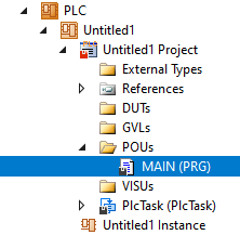
- 1. Use MAIN to create the mover(s) ("MC_PlanarMover") as follows.
- This/these represent(s) the mover(s) in the MC Configuration.
- 2. Create a Planar mover, a Planar environment, a Planar part, a state variable for a state machine and a target position for a travel command of the mover, as shown below.
PROGRAM MAIN
VAR
    mover : MC_PlanarMover;
    environment : MC_PlanarEnvironment;
    part_three : MC_PlanarPart;
    state : UDINT;
    target_position : PositionXYC;
END_VAR- 3. Then program a sequence in MAIN.
- This program code initializes part 3, activates the mover, moves part 3 to coordinate system 1, moves the mover to part 3, moves part 3 back to coordinate system 2 and finally moves the mover to part 2 in coordinate system 2.
CASE state OF
  0:
    part_three.Initialize(0, 16#01010080, environment);
    state := 1;
  1:
    IF part_three.IsInitialized THEN
      state := 2;
    END_IF
  2:
    mover.Enable(0);
    state := 3;
  3:
    IF mover.MCTOPLC.STD.State = MC_PLANAR_STATE.Enabled THEN
      state := 4;
    END_IF
  4:
    part_three.ActivatePosition(0,1);
    state := 5;
  5:
    IF part_three.PositionIndex = 1 THEN
      state := 6;
    END_IF
  6:
    target_position.SetValuesXYCReferenceId(120, 120, 0, part_three.PartOID);
    mover.MoveToPosition(0, target_position, 0, 0);
    state := 7;
  7:
    IF mover.MCTOPLC.SET.SetPos.y > 300 AND NOT mover.MCTOPLC.STD.Busy.busyXYC THEN
      state := 8;
    END_IF
  8:
    part_three.ActivatePosition(0,2);
    state := 9;
  9:
    IF part_three.PositionIndex = 2 THEN
      state := 10;
    END_IF
  10:
    target_position.SetValuesXYCReferenceId(120, 120, 0, 16#01010030); // Position on part two
    mover.MoveToPosition(0, target_position, 0, 0);
    state := 11;

END_CASE
Sending the command
- 4. To send the motion command, you must call the mover cyclically with its update method after the END_CASE; to send the commands of the Planar part, the environment must be called cyclically with its update method:
mover.Update();
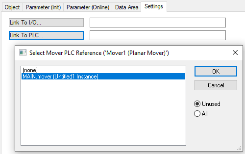
environment.Update();When creating the PLC, a symbol of the "PLC Mover" is created, which can then be linked to the mover instance in the MC project.
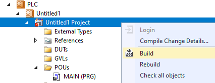
- 1. To build, use the path PLC > Untitled1 > Untitled1 Project > Build.
- Subsequently, the Planar mover in the "MC Project" (double-click) can be linked with the Link To PLC... button on the Settings tab.
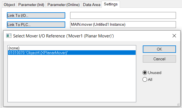
- In addition, the Planar mover in the "MC Project" (double-click) can be linked with the Link To I/O... button on the Settings tab.
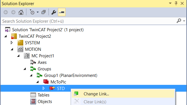
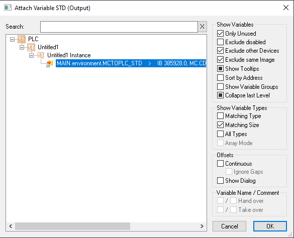
- The Planar environment can then be linked in the "MC Project".
Activating and starting the project
- 1. Activate the configuration via the button in the menu bar
 .
. - 2. Set the TwinCAT system to the "Run" state via the button
 .
. - 3. Log in the PLC via the button in the menu bar
 .
. - 4. Start the PLC via the Play button in the menu bar.
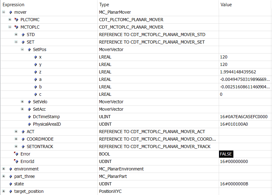
At the end of the state machine (state = 11, shown in hexadecimal in the figure below as B), the mover is in the desired position. The position is specified in coordinate system two (object Id 16#010100A0). The mover has changed the coordinate system together with part 3, or has moved to a different level with the elevator. Overall, the example clearly shows that the Planar-Part PLC objects are only lightweight environment wrappers that have to be initialized with the environment and send their commands via the environment.