Configuration
- In order to create a Planar environment, an MC Configuration must first be created.
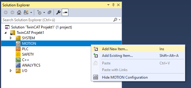
- 1. Select MOTION > Add New Item….
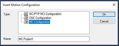
- 2. In the following dialog box, select MC Configuration and confirm with OK.
- You have created an MC Project.
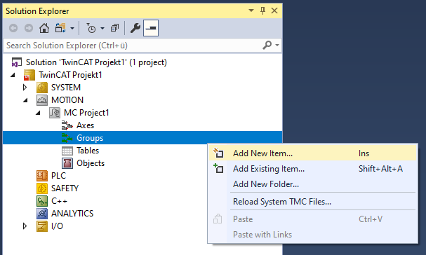
- 3. Select MC Project > Groups > Add New Item….
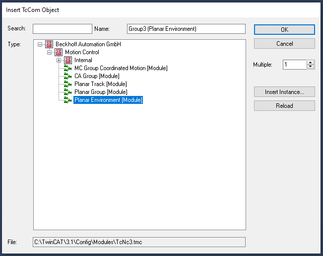
- 4. In the following dialog box, create one (or more) Planar environments and confirm with OK.
- The Planar environment is now created and can be parameterized.
Open detailed description
- Select the Planar environment in the tree and double-click it.
Purposes of the individual tabs
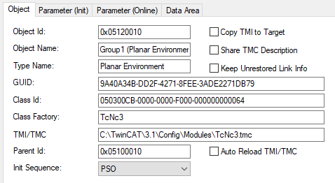
Object: General information (name, type, ID and so on) is shown here.
Parameter (Init): Specifies initial parameters that the user can change in order to affect the behavior of the environment.
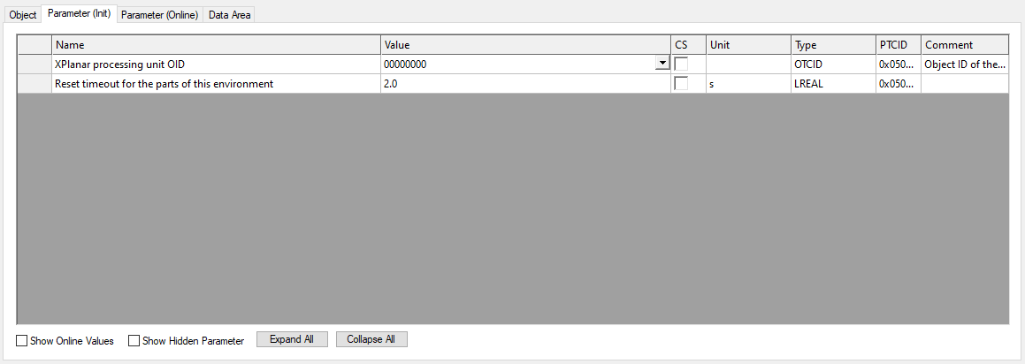
The environment has the initial "XPlanar processing unit OID" parameter. When this (>0) is set to the object ID of the XPlanar processing unit, the environment automatically reads the stator configuration from the XPlanar processing unit and generates the boundary elements for collision detection from this information. This takes place as soon as the user calls the CreateBoundary() command in the PLC.
The hidden initial parameter "TraceLevel" influences how much information is logged (see Logging/Tracing).
If the "XPlanar processing unit OID" parameter is set to the object ID of the XPlanar processing unit, the environment also reads the part configuration from the XPlanar processing unit and generates an internal representation of all parts. This is used both to perform collision checks with the edge of the parts when the environment is in the Planar group and to provide all components (movers, tracks, group) with a complete system description.
The "Timeout for state machine" parameter specifies the maximum time the Planar parts remain in Enabling or Resetting, see "Timeouts of the transition states" in Planar objects state diagram.
Parameter (Online): Shows the state of the environment during the runtime of the object.

The number of stators inserted into the environment and the boundary elements calculated from them are displayed here.
The "PartCount" parameter specifies the number of parts read out and created internally. The "PlanarPartsInfo" parameter displays information for all parts. This information consists of the object ID of the part, the Planar state of the part, the active position index, the position of the part consisting of the object ID of the coordinate system and x/y coordinates, and the "disableForced" flag of the part.
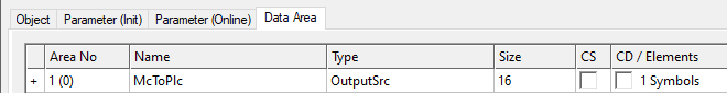
Data Area: Shows the memory area via which the group communicates with the PLC environment.