Configuration
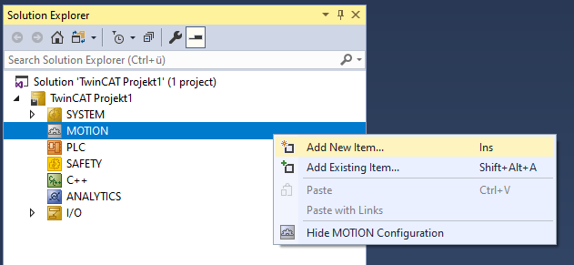
- In order to create a Planar mover, an MC Configuration must first be created.
- 1. Select MOTION > Add New Item….
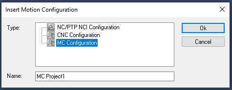
- 2. In the following dialog box, select MC Configuration and confirm with OK.
- You have created an MC Project.
- 3. Select MC Project > Axes > Add New Item….
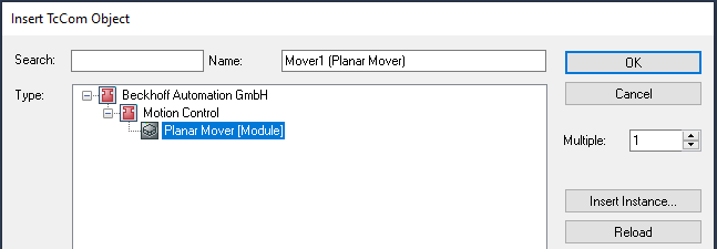
- 4. In the following dialog box, create one (or more) Planar movers and confirm with OK.
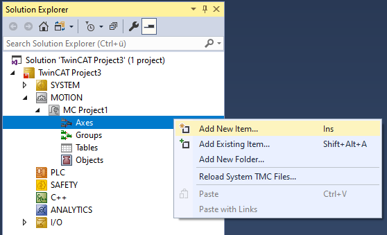
- The Planar mover is now created and can be parameterized.
Open detailed description
- Select the Planar mover in the tree and double-click it.
Purposes of the individual tabs
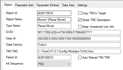
Object: General information (name, type, ID and so on) is shown here.
Parameter (Init): Specifies initial parameters that the user can change in order to affect the behavior of the mover.
 | Parameter (Init) should be put into simulation mode ( |
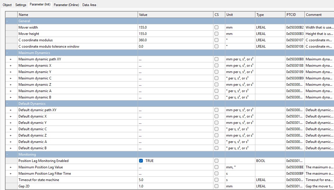
The initial parameters are initially set so that the Planar mover (ready linked) can be moved with the hardware. If the user wants to proceed without hardware, the hidden "Simulation Mode" parameter must be set to TRUE. In simulation mode, the “Initial Position” and “PartOID” parameters, which are also hidden, should be set. If the real mover does not have standard dimensions, the "Mover width" and "Mover height" parameters must be adjusted.
The hidden "Minimum/Maximum Position" parameters are used to define when the mover switches to the CRotation command mode for the C axis. For maximum/minimum values of +/-45°, the mover never switches to the CRotation command mode. For all target positions of C-movements, the "C coordinate modulus" and "C coordinate modulo tolerance window" parameters (the latter for modulo positioning) define the conversion to the absolute target position. For details see Modulo positioning.
AdoptTrackOrientation is also a C-movement and is accordingly influenced by "C coordinate modulus" and "C coordinate modulo tolerance window". For details, see AdoptTrackOrientation.
The "PartOID", "Simulation Mode", and "Initial Position" parameters are all hidden and in their own "Simulation" grouping.
Other parameters are the "Maximum Dynamic(s)" and the "Default Dynamic(s)". In addition, there are "monitoring" parameters that activate or parameterize position monitoring of the real mover.
The "Maximum dynamic path XY" and "Default dynamic path XY" parameters apply tangentially to the mover's direction of movement. For example, they apply tangentially to the track in the OnTrack command mode.
The coordinate-based default and maximum dynamics apply to the corresponding coordinate-based motion commands, see Example "Create Planar movers and move based on coordinates (MoveX, MoveY)" and Example: "Creating and moving a Planar mover with auxiliary axes".
The "Maximum dynamic X" and "Maximum dynamic Y" parameters also apply to the OnTrack command mode. Only the acceleration parameter A has an effect here. It is used to set the maximum radial acceleration in curves when the "AccelerationLimitedVelocity" option is enabled in "DynamicsReductionMode" and you are driving on a track. For details, see Limits and options of the motion commands.
The "Timeout for state machine" parameter specifies the maximum time the mover remains in Enabling, Disabling or Resetting, see "Timeouts of the transition states" in Planar objects state diagram.
From version V3.4.45: The "Gap 2D" parameter specifies the minimum distance that a mover maintains to other objects when moving with dynamic 2D collision avoidance.
The parameters "Minimum/Maximum Position", "Default/Maximum Dynamic(s)", "C coordinate modulus", "C coordinate modulo tolerance window" and all "Monitoring" parameters (position monitoring/timeout/gap) can be changed in the Enabled state of the mover. Previously, this was only possible with Disabled.
The hidden initial parameter "TraceLevel" influences how much information is logged (see Logging/Tracing).
Parameter (Online): Shows the state of the mover during the runtime of the object. The current preset position ("SetPos") and real position ("ActPos") are displayed along with the state information.
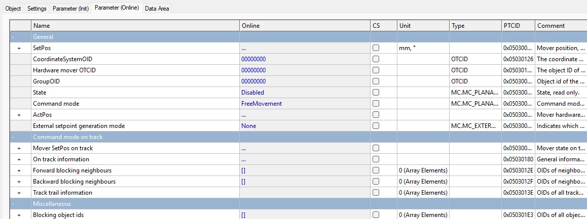
The "External setpoint generation" parameter indicates whether the mover follows (absolute or relative) external setpoints of the user.
The "CoordinateSystemOID" parameter specifies the coordinate system in which SetPos and ActPos are specified and the coordinate system in which the mover is located.
As of version V3.4.60: The parameters “On track information,” “Forward blocking neighbors,” “Backward blocking neighbors,” and “Track trail information” provide specific information about the mover’s current state on the track.
As of version V3.4.45: The "Blocking object ids" parameter specifies 0–3 other Planar objects that block this mover in dynamic 2D collision avoidance. Blocking can occur in the three movement directions X, Y, and C during free movement.
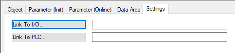
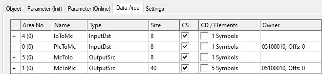
Data Area: Shows memory areas via which the mover is linked to other objects and exchanges information.
Settings: The user can establish links here. With the two "Link To ..." buttons, the Planar mover can be linked to the movers in the PLC and the XPlanar driver.