Example "Moving Planar movers on tracks with Planar parts"
In this example, a Planar mover is moved on two Planar tracks over two Planar parts.
Starting point
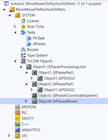
You start with a solution that contains a fully configured XPlanar Processing Unit. Two parts, a coordinate system and a mover are created under the XPlanar Processing Unit. A tile is created under each of the two parts.
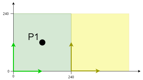
The following geometric situation is set: the two parts are next to each other and the mover starts in the middle of the left part (position P1). Both parts are not movable and the configuration is therefore static.
The example is developed on the basis of this configuration.
 | The creation of the initial situation is described in the XPlanar Processing Unit documentation. |
Creating Planar movers, Planar tracks and Planar environment
- 1. Create a Planar mover for this example, see Configuration.
- 2. Create a Planar environment, see Configuration.
- 3. Set the initial parameter XPlanar processing unit OID to the object ID of the XPlanar Processing Unit. This activates the Part feature for all MC Configuration objects (especially for the created Planar mover).
- 4. Add two Planar tracks via Groups > Add New Item…, see Configuration.
- 5. Set the initial parameter “PartOID” of the two tracks to the corresponding part; in this example, the first track is set to part 1 and the second track to part 2.
Creating a PLC
- See preliminary steps under Creating a PLC.
- 1. Create the desired number of movers ("MC_PlanarMover") and tracks ("MC_PlanarTrack") via MAIN.
- These represent movers and tracks in the MC Configuration.
- 2. Create a Planar mover, two Planar tracks, a state variable for a state machine and two auxiliary positions for the tracks, as shown below.
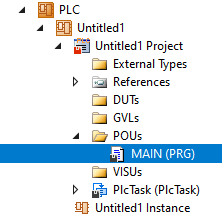
PROGRAM MAIN
VAR
    mover : MC_PlanarMover;
    track_one, track_two : MC_PlanarTrack;
    state : UDINT;
    pos1, pos2 : PositionXYC;
END_VAR- 3. Then program a sequence in MAIN.
- This program code creates and activates two tracks and the mover. The mover is then coupled onto the first track and driven onto the second track, crossing the boundary between Part 1 and Part 2.
CASE state OF
  0:
    pos1.SetValuesXYCReferenceId(40, 120, 0, 16#01010060);
    pos2.SetValuesXYCReferenceId(240, 120, 0, 16#01010060);
    track_one.AppendLine(0, pos1, pos2);
    track_two.StartFromTrack(0, track_one);
    pos1.SetValuesXYCReferenceId(260, 120, 0, 16#01010060);
    pos2.SetValuesXYCReferenceId(440, 120, 0, 16#01010060);
    track_two.AppendLine(0, pos1, pos2);
    track_one.Enable(0);
    track_two.Enable(0);
    state := 1;
  1:
    IF track_one.MCTOPLC_STD.State = MC_PLANAR_STATE.Enabled AND
    track_two.MCTOPLC_STD.State = MC_PLANAR_STATE.Enabled THEN
      state := 2;
    END_IF
  2:
    mover.Enable(0);
    state := 3;
  3:
    IF mover.MCTOPLC.STD.State = MC_PLANAR_STATE.Enabled THEN
      state := 4;
    END_IF
  4:
    mover.JoinTrack(0, track_one, 0, 0);
    state := 5;
  5:
    IF mover.MCTOPLC.STD.CommandMode = MC_PLANAR_MOVER_COMMAND_MODE.OnTrack THEN
      state := 6;
    END_IF
  6:
    mover.MoveOnTrack(0, track_two, 150.0, 0, 0);
    state := 7;

END_CASE
Sending the command
- 4. To send the command, you must call the movers and the track cyclically with their update method after the END_CASE:
mover.Update();
track_one.Update();
track_two.Update();
Building the PLC creates symbols of the "PLC mover" and “track”, which can then be linked to the mover and track instance in the MC project.
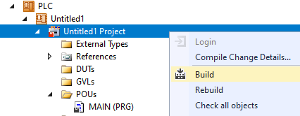
- 1. To build, use the path PLC > Untitled1 > Untitled1 Project > Build.
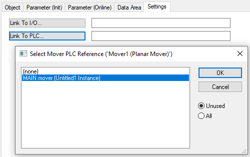
- Subsequently, the Planar movers in the “MC Project” can be linked with the Link To PLC... button on the Settings tab.
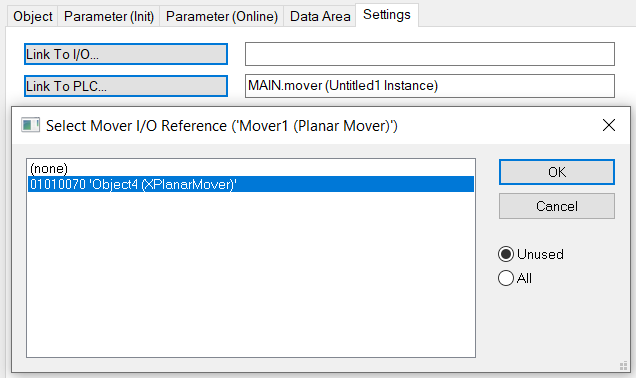
- In addition, the Planar mover in the “MC Project” (double-click) can be linked with the Link To I/O... button on the Settings tab.
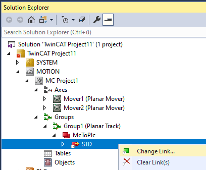
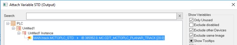
The tracks must be linked separately via the following dialog boxes.
Activating and starting the project
- 1. Activate the configuration via the button in the menu bar
 .
. - 2. Set the TwinCAT system to the "Run" state via the button
 .
. - 3. Log in the PLC via the button in the menu bar
 .
. - 4. Start the PLC via the Play button in the menu bar.
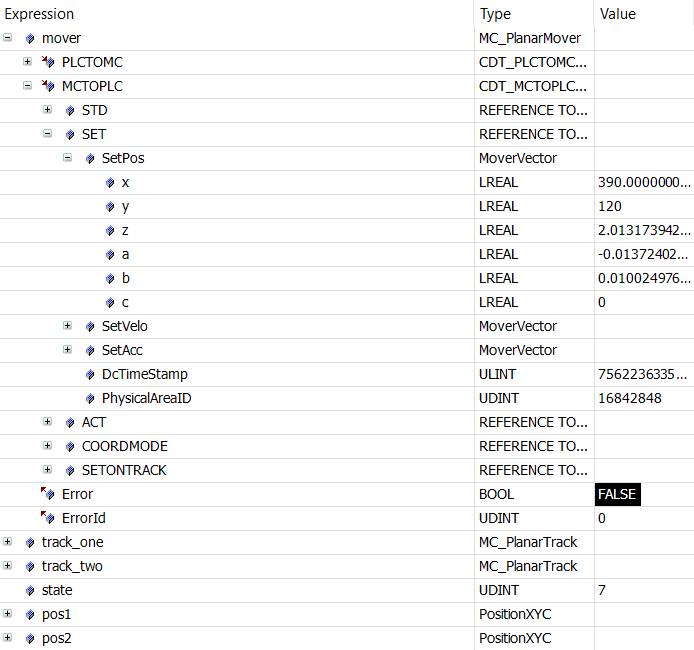
The mover is at the end of the state machine (state=7) on the second track on part two. The positions of the AppendLine commands were specified in the global coordinate system, as was the end position of the mover.