Example "Moving a Planar mover with External Setpoint Generation to Planar parts"
In this example, a Planar mover is moved to two Planar parts with external setpoint generation.
Starting point
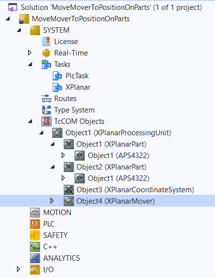
You start with a solution that contains a fully configured XPlanar Processing Unit. Two parts, a coordinate system and a mover are created under the XPlanar Processing Unit. A tile is created under each of the two parts.
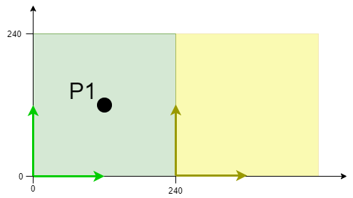
The following geometric situation is set: the two parts are next to each other and the mover starts in the middle of the left part (position P1). Both parts cannot be moved; the configuration is therefore static.
The example is developed on the basis of this configuration.
 | The creation of the initial situation is described in the XPlanar Processing Unit documentation. |
Creating a Planar mover and a Planar environment
- 1. Create a Planar mover for this example, see Configuration.
- 2. Create a Planar environment, see Configuration.
- 3. Set the initial parameter XPlanar processing unit OID to the object ID of the XPlanar Processing Unit. This activates the Part feature for all MC Configuration objects (especially for the created Planar mover).
Creating a PLC
- See preliminary steps Creating a PLC.
- 1. Use MAIN to create the mover(s) ("MC_PlanarMover") as follows.
- This/these represent(s) the mover(s) in the MC Configuration.
- 2. Create a Planar mover, a state variable for a state machine and variables for the external setpoint, as shown below.
PROGRAM MAIN
VAR
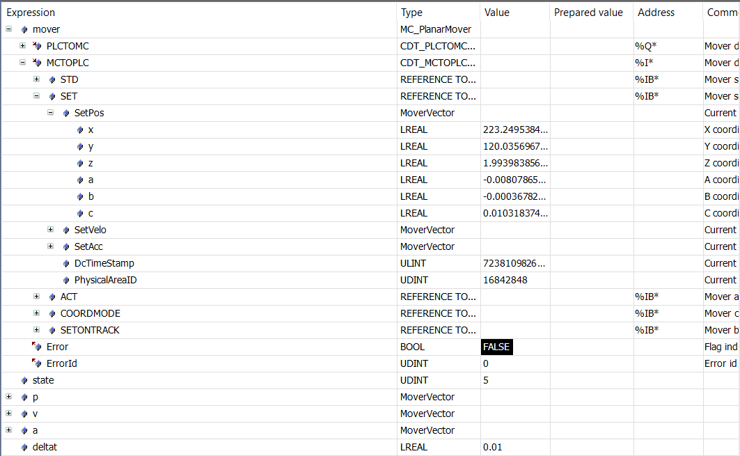
mover : MC_PlanarMover;
state : UDINT;
p,v,a : MoverVector;
deltat : LREAL := 0.01;
refsys : OTCID := 0;
jerk : LREAL := 1.0;
velo, acc, jerk : LREAL;
feedback : MC_PlanarFeedback;
END_VAR- 3. Then program a sequence in MAIN.
- This program code activates the mover and starts the external setpoint generation. A profile is then followed that ends with a positive velocity. The subsequent stopping of the external setpoint generation ensures that the mover reduces its velocity to zero and is in the FreeMovement state after stopping (this is done with the maximum dynamics of the mover).
CASE state OF
  0:
    mover.Enable(0);
    state := 1;
  1:
    IF mover.MCTOPLC.STD.State = MC_PLANAR_STATE.Enabled THEN
      state := 2;
    END_IF
  2:
    p := mover.MCTOPLC.SET.SetPos;
    v.x := 0.0; a.x := 0.0;
    mover.StartExternalSetpointGeneration(0,0);
    mover.SetExternalSetpointReferenceId(feedback,p,v,a,refsys);
    jerk := 10;
    state := 3;
  3:
    velo := v.x;
    acc := a.x;
    p.x := p.x + deltat * velo + deltat * deltat / 2 * acc + deltat * deltat * deltat / 6 * jerk;
    v.x := velo + deltat * acc + deltat * deltat / 2 * jerk;
    a.x := acc + deltat * jerk;
    mover.SetExternalSetpointReferenceId(feedback,p,v,a,refsys);
    IF a.x >= 100.0 THEN
      jerk := -10;
    END_IF;
    IF a.x <= 0.0 THEN
      state := 4;
    END_IF;
  4:
    mover.StopExternalSetpointGeneration(0);
    state := 5;

END_CASE
Sending the command
- 4. To send the commands you need to trigger the update method of the mover after the END_CASE:
mover.Update();When creating the PLC, a symbol of the "PLC Mover" is created, which can then be linked to the mover instance in the MC project.
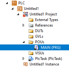
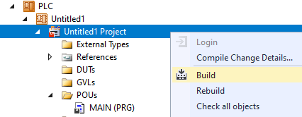
- 1. To build, use the path PLC > Untitled1 > Untitled1 Project > Build.
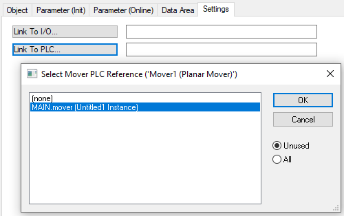
- Subsequently, the Planar mover in the "MC Project" (double-click) can be linked with the Link To PLC... button on the Settings tab.
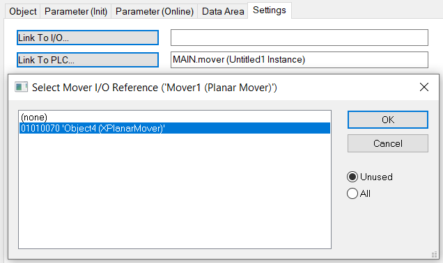
- In addition, the Planar mover in the "MC Project" (double-click) can be linked with the Link To I/O... button on the Settings tab.
Activating and starting the project
- 1. Activate the configuration via the button in the menu bar
 .
. - 2. Set the TwinCAT system to the "Run" state via the button
 .
. - 3. Log in the PLC via the button in the menu bar
 .
. - 4. Start the PLC via the Play button in the menu bar.
At the end of the state machine (state = 5), the mover is in the desired positive x-position. It has not left the first part, so in this case you could also specify the object ID of the first part or the coordinate system as refsys. If the object ID of the first part is specified and the limit to the second part is exceeded, the object ID of the second part must be used and the x-coordinate reduced by 240 (at the same time!). The object ID of the global coordinate system works regardless of which part the mover is on. As the configuration is static, zero is accepted as an alternative for the global coordinate system ID.
Comments on the feedback:
In this example, the feedback was only created and entered in the SetExternalSetpointRefSys call without doing anything with it. As no errors occur in this example, the feedback is busy from state 2. Otherwise, you should ALWAYS implement error handling with this feedback in order to handle errors such as an incorrect RefSysId for the position.
The special feature of this feedback is that it is passed cyclically and the same feedback must be passed in every call. If errors occur in the external setpoint generation, these errors are displayed in the feedback after the next call of SetExternalSetpointRefSys with feedback. An update call for the feedback is not necessary here. In addition, the feedback is not done when StopExternalSetpointGeneration is called, or aborted when Halt is called.
Even if the information is available in the feedback after the SetExternalSetpointRefSys call, the errors do not have to come directly from this call, but can also result from previous calls.