FB_DALI102ConstantLightControl
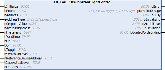
The FB_DALI102ConstantLightControl function block provides the basic functions for implementing constant light regulation.
The system attempts to regulate to a specified setpoint (nSetpointValue) by dimming up and down cyclically. The control dynamics are determined by a dead time (tDeadTime). The dead time defines the settling time between the individual DALI commands for changing the output value (nActualLevel). The smaller the dead time, the faster the control. A freely definable hysteresis (nHysteresis) prevents continuous oscillation around the setpoint. If the actual value is within the hysteresis range around the setpoint, the output value of the DALI control gears is not changed.
Operation
The function block offers the option to address a single DALI control gear via a short address, several DALI control gears via a group address, or all DALI control gears of a DALI line via a broadcast.
The variables minLevel, maxLevel, fadeRate, fadeTime, extendedFadeTimeBase and extendedFadeTimeMultiplier are parameters that are stored separately in each DALI control gear. These variables can be changed in the DALI control gears by writing to the respective properties and with a positive edge at the input bInitialize.
Control
The output value of the DALI control gears can be switched by positive edges at the inputs bOn, bOff and bToggle. If the DALI control gears are switched on and control is active (bEnable = TRUE), then they are regulated to the specified setpoint. If the control is not active (bEnable = FALSE), the output value of the DALI control gears remains unchanged.
The step-by-step adaption of the output value of the DALI control gears is carried out with the DALI commands STEP UP/STEP DOWN or UP/DOWN.
If the control deviation (nDeviation) is greater than nHysteresis, the DALI command UP/DOWN is used to adjust the output value. The number of steps by which the output value changes is specified by the eFadeRate property.
If the control deviation is between nHysteresis/2 and nHysteresis, the DALI command STEP UP/STEP DOWN is used and thus the output value is only adjusted by one step.
If the control deviation is smaller than nHysteresis/2, the output value of the DALI control gears remains unchanged.
The control deviation is calculated from nSetpointValue - nActualBrightness.
The dead time (tDeadtime) specifies the time after which the output value is adapted. The DALI command STEP UP/STEP DOWN or UP/DOWN is called only once per control cycle.
Operation via the inputs bOn, bOff, and bToggle
The output value of the DALI control gears can be changed immediately by positive edges at the inputs bOn, bOff, and bToggle. This is independent of whether the control has been enabled or disabled (bEnable).
The variables fadeTime, extendedFadeTimeBase, and extendedFadeTimeMultiplier specify the speed at which the output value is changed when the DALI control gears are switched on via bOn or bToggle. Switching off the DALI control gears by bOff or bToggle takes place immediately. In this case, nSwitchOnLevel is used as the switch-on value. This value must lie in the range of the properties nMinLevel and nMaxLevel.
DALI short address reference device (nReferenceDeviceAddress)
If several DALI control gears are addressed, the current output value of the reference DALI control gear is read out via nReferenceDeviceAddress. The DALI control gears are set to the desired output value, depending on the state of the reference DALI control gear.
The parameter nReferenceDeviceAddress is also used if the output value of the reference DALI control gear is read out cyclically in the background (tCycleActualLevel > 0 sec).
No reference DALI control gear is required if a single DALI control gear is to be controlled with the function block (eAddressType = E_DALIAddressType.Short). The output value of the individual DALI control gear is determined via nAddress. The parameter nReferenceDeviceAddress has no meaning in this case.
If nReferenceDeviceAddress is used, it must always contain the short address of a DALI control gear, which is also contained in the addressed DALI group. For a broadcast a DALI control gear with the corresponding short address must be present on the DALI line.
Sample
The following sample shows how a DALI light sensor can be combined with the FB_DALIConstantLightControl function block. In this sample, the PD11-BMS-FLAT DALI sensor from B.E.G. is used.
Since only the measured brightness is required, the instance for the movement sensor is disabled (property bEnableOccupancy).
The brightness is read out from the DALI sensor via the input bQueryBrightness. Thus, the instance for the light sensor can also be disabled (property bEnableBrightness).
At the end of the dead time, the output bControlCyclerEnding of the constant light regulation is set to TRUE. This positive edge is connected to the input bQueryBrightness of the DALI sensor. This means that the current brightness value is read out immediately before calculating the control deviation (nDeviation).
 | By deactivating both instances, the DALI sensor does not send any events and the DALI bus is not unnecessarily loaded. |
The properties are initialized directly when the instance is declared. This means that explicit assignment at runtime is no longer necessary.
PROGRAM P_ConstantLightControl
VAR
  fbBrightness           : FB_DALI_BEG_PD11_BMS_V8_Flat(Communication.fbKL6821Communication) :=
                                 (bEnableOccupancy  := FALSE,
                                  bEnableBrightness := FALSE);
  fbConstantLightControl : FB_DALI102ConstantLightControl(Communication.fbKL6821Communication) :=
                                 (nMinLevel := 85,
                                  nMaxLevel := 254);
  bInitialize            : BOOL;
  bToggle                : BOOL;
  nBrightnessLevel       : UINT;
  nActualLevel           : BYTE;
  nDeviation             : DINT;
END_VAR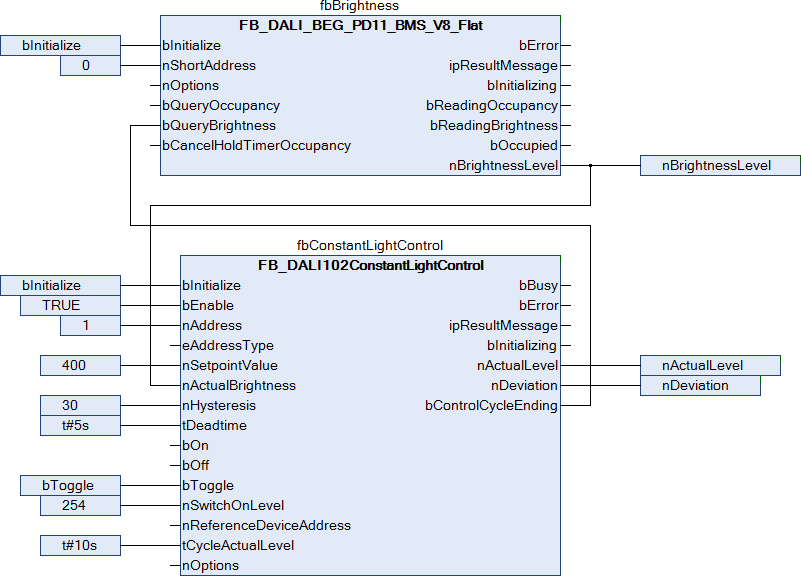
 Inputs
VAR_INPUT
  bInitialize              : BOOL := FALSE;
  bEnable                  : BOOL := TRUE;
  nAddress                 : BYTE;
  eAddressType             : E_DALIAddressType := E_DALIAddressType.Short;
  nSetpointValue           : UINT := 500;
  nActualBrightness        : UINT := 500;
  nHysteresis              : UINT := 30;
  tDeadtime                : TIME := T#5S;
  bOn                      : BOOL;
  bOff                     : BOOL;
  bToggle                  : BOOL;
  nSwitchOnLevel           : BYTE := 254;
  nReferenceDeviceAddress  : BYTE;
  tCycleActualLevel        : TIME := T#30S;
  nOptions                 : DWORD := 0;
END_VAR
Name | Type | Description |
|---|---|---|
bInitialize | BOOL | A positive edge at this input writes the values of all properties to the DALI control gears. Writing the properties to the DALI control gears is only possible if no other functions are being executed by the function block (bBusy = FALSE). |
bEnable | BOOL | Activates constant light regulation as soon as this input is TRUE. If the input is FALSE, the constant light regulation is disabled. |
nAddress | BYTE | Address of a DALI control gear or a DALI group. |
eAddressType | Defines whether the input nAddress contains a short address (0…63) or a group address (0…15). The input nAddress has no meaning if a broadcast or a broadcast to unaddressed devices (BroadcastUnaddr) has been selected. | |
nSetpointValue | UINT | The setpoint is applied to this input (0...65535). |
nActualBrightness | UINT | The actual value is applied at this input. |
nHysteresis | UINT | Control hysteresis (1...65535) around the setpoint. If the actual value is within this range, the output values of the DALI control gears are not changed. |
tDeadtime | TIME | After the dead time (2...3600 s) has elapsed, the control deviation is recalculated and, if necessary, the output values of the DALI control gears are reduced or increased. |
bOn | BOOL | A positive edge at this input sets the DALI control gears to nSwitchOnLevel. |
bOff | BOOL | The DALI control gears are switched off via a positive edge at this input. |
bToggle | BOOL | A positive edge at this input toggles the DALI control gears between Off and nSwitchOnLevel. |
nSwitchOnLevel | BYTE | Output value (minLevel...maxLevel) for switching on the DALI control gears by the bOn and bToggle inputs. |
nReferenceDeviceAddress | BYTE | Short address (0...63) of the reference DALI control gear for group call and broadcast. This parameter is not evaluated if eAddressType = E_DALIAddressType.Short. In this case, the reference DALI control gear is read out via nAddress. |
tCycleActualLevel | TIME | Cycle time with which the current output value of the reference DALI control gear is read out in the background. Set the cycle time such that as few DALI commands as possible are sent. If the time is set to 0 sec, no reading takes place. |
nOptions | DWORD | Reserved for future extensions. |
Constant | Description |
|---|---|
Tc3_DALI.GVL.cMemoryMode | Activates memory mode. |
 Outputs
VAR_OUTPUT
  bError               : BOOL;
  ipResultMessage      : I_TcMessage;
  bBusy                : BOOL;
  bInitializing        : BOOL;
  nActualLevel         : BYTE;
  nDeviation           : DINT;
  bControlCycleEnding  : BOOL;
END_VAR
Name | Type | Description |
|---|---|---|
bError | BOOL | This output is switched to TRUE if an error occurs during the execution. Further information about the error can be queried via the variable ipResultMessage. The output is set to FALSE again as soon as bBusy switches to TRUE. |
ipResultMessage | I_TcMessage | Interface pointer (see error evaluation) that can be used to obtain detailed information about the processing of the function block (see runtime messages). The interface pointer is valid after bBusy has changed from TRUE to FALSE. |
bBusy | BOOL | The output is set as soon as execution of the DALI commands has commenced. It remains active until all DALI commands have been processed. For some errors (e.g. faulty parameters), bError is set immediately after the positive edge at bStart without bBusy switching to TRUE. |
bInitializing | BOOL | The output is set as soon as the initialization of the DALI control gears has been started, and remains active until all DALI commands have been executed. |
nActualLevel | BYTE | Current output value (0, minLevel...maxLevel, 255) of the reference DALI control gear that is addressed via nReferenceDeviceAddress. If eAddressType = E_DALIAddressType.Short, the reference DALI control gear is read out via nAddress. A value of 255 (MASK) indicates that an error occurred while reading the output value from the reference DALI control gear. The cause could be, for example, a technical defect or that the DALI control gear is in the start-up phase. In this case bError is not set to TRUE. |
nDeviation | DINT | Current control deviation (nSetpointValue - nActualBrightness) |
bControlCycleEnding | BOOL | Before the dead time(tDeadtime) expires, this output is set to TRUE for 500 ms. This output can be used, for example, to read the current brightness from a DALI light sensor. |
 Properties
All parameters that are written to the DALI control device via bInitialize are available as properties.
Name | Type | Access | Initial value | Description |
|---|---|---|---|---|
nMaxLevel | BYTE | Get, Set | 254 | See variable maxLevel. |
nMinLevel | BYTE | Get, Set | 126 | See variable minLevel. |
eFadeRate | E_DALIFadeRate | Get, Set | N045StepsPerSec | See variable fadeRate. |
eFadeTime | E_DALIFadeTime | Get, Set | Disabled | See variable fadeTime. |
eExtendedFadeTimeBase | E_DALIExtendedFadeTimeBase | Get, Set | Base01 | See variable extendedFadeTimeBase. |
eExtendedFadeTimeMultiplier | E_DALIExtendedFadeTimeMultiplier | Get, Set | Disabled | See variable extendedFadeTimeMultiplier. |
ipDALICommunication | I_DALICommunication | Get, Set | NULL | Interface pointer to the communication block (see Transfer of the reference to the communication block). |
Requirements
Development environment | Required PLC library |
|---|---|
TwinCAT from v3.1.4024.25 | Tc3_DALI from v3.10.5.0 |