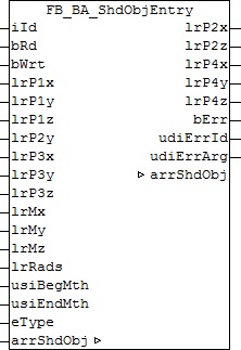
FB_BA_ShdObjEntry
This function block serves for the administration of all shading elements in a facade, which is globally saved in a list of shading elements. It is intended to facilitate the input of the element information - also regarding the use of the target visualisation. A schematic representation of the objects with description of the coordinates is shown in Shading correction: principles and definitions.
Functional description
The shading elements are declared in the global variable:
VAR_GLOBAL
     arrShadingObject : ARRAY[1..iShadingObjects] OF ST_BA_ShdObj;
END_VAR
Each individual element arrShadingObject[1] to arrShadingObject[gBA_cMaxShdObj] carries the information for one shading element (ST_BA_ShdObj). This information consists of the selected type of shading (rectangle or sphere) and the respectively associated coordinates. For a rectangle, these are the corner points (lrP1x, lrP1y, lrP1z), (lrP2x, lrP2y, lrP2z),(lrP3x, lrP3y, lrP3z) and (lrP4x, lrP4y, lrP4z), for a sphere this are the center point (lrMx, lrMy, lrMz) and the radius lrRads. In addition, the phase of the shading can be defined via the inputs usiBegMth and usiEndMth, which is important in the case of objects such as trees that bear no foliage in winter.
The function block thereby directly accesses the field of this information via the IN-OUT variable arrShadingObject.
Note: The fact that the rectangle coordinates lrP2x, lrP2z, lrP4x, lrP4y and lrP4z are output values results from the fact that they are formed from the input parameters:
lrP2x = lrP1x; lrP2z = lrP1z; lrP4x = lrP3x; lrP4y = lrP1y; lrP4z = lrP3z;
That limits the input of a rectangle to the extent that the lateral edges stand vertically on the floor (lrP2x = lrP1x and lrP4x = lrP3x), that the rectangle has no inclination (lrP2z = lrP1z and lrP4z = lrP3z) and can only have a different height "upwards", i.e. in the positive y-direction (lrP4y = lrP1y).
The function block is used in three steps:
- Read
- Change
- Write
Read
With the entry to iId the appropriate element is selected from the list arrShadingObject[iId]. A rising edge on bRd reads the data. These values are assigned to the input and output variables of the function block. These are the input values lrP1x, lrP1y, lrP1z, lrP2y, lrP3x, lrP3y, lrP3z, lrMx, lrMy, lrMz, rRadius, the object enumerator eType and the output values lrP2x, lrP2z, lrP4x, lrP4y and lrP4z. It is important here that the input values are not overwritten in the reading step. Hence, all values can initially be displayed in a visualization.
Change
In a next program step the listed input values can then be changed. If the use of a rectangle is preselected via the value "eObjectTypeTetragon" at the input eType, then the output values lrP2x, lrP2z, lrP4x, lrP4y and lrP4z result from the rectangle coordinates entered, see above.
The values entered are constantly checked for plausibility. The output bErr indicates whether the values are valid (bErr=FALSE). If this is not the case, a corresponding error code is output at udiErrId/udiErrArg.
If a rectangle is defined, then only the inputs lrP1x, lrP1y, lrP1z, lrP2y, lrP3x, lrP3y and lrP3z need to be described; the inputs lrMx, lrMy, lrMz and lrRads do not need to be linked. In case of a ball definition, only lrMx, lrMy, lrMz and lrRads need to be described and the rectangle coordinates can remain unlinked.
Write
The parameterised data are written to the list element with the index iId upon a rising edge on bWrt, regardless of whether they represent valid values or not. The element structure ST_BA_ShdObj therefore contains a plausibility bit bVld, which forwards precisely this information to the function block FB_BA_ShdCorr to prevent miscalculations.
This approach is to be regarded only as a proposal. It is naturally also possible to parameterise the function block quite normally in one step and to write the values entered to the corresponding list element with a rising edge on bWrt.
Inputs/outputs
VAR_INPUT
iId            : INT;
bRd            : BOOL;
bWrt           : BOOL;
lrP1x          : LREAL;
lrP1y          : LREAL;
lrP1z          : LREAL;
lrP2y          : LREAL;
lrP3x          : LREAL;
lrP3y          : LREAL;
lrP3z          : LREAL;
lrMx           : LREAL;
lrMy           : LREAL;
lrMz           : LREAL;
lrRads         : LREAL;
usiBegMth      : USINT;
usiEndMth      : USINT;
eType          : E_BA_ShdObjType;
iId: index of the selected element. This refers to the selection of a field element of the array stored in the IN-OUT variable arrShdObj. iId may not be zero! This is due to the field definition, which starts with 1; see above.
bRd: the information of the selected element, arrShdObj[iId], is read into the function block with a positive edge at this input and assigned to the input variables lrP1x to eType and the output variables lrP2x to lrP4z. If at this time data have already been applied to the inputs lrP1x to eType, the previously read data are immediately overwritten with these.
bWrt: a positive edge writes the values applied to inputs lrP1x to eType and the values determined and assigned to outputs lrP2x to lrP4z to the selected field element arrShdObj[iId].
lrP1x: X-coordinate of point 1 of the shading element (rectangle) [m]
lrP1y: Y-coordinate of point 1 of the shading element (rectangle) [m]
lrP1z: Z-coordinate of point 1 of the shading element (rectangle) [m]
lrP2y: Y-coordinate of point 2 of the shading element (rectangle) [m]
lrP3x: X-coordinate of point 3 of the shading element (rectangle) [m]
lrP3y: Y-coordinate of point 3 of the shading element (rectangle) [m]
lrP3z: Z-coordinate of point 3 of the shading element (rectangle) [m]
lrMx: X-coordinate of the center of the shading element (sphere) [m]
lrMy: Y-coordinate of the center of the shading element (sphere) [m]
lrMz: Z-coordinate of the center of the shading element (sphere) [m]
lrRads: radius of the shading element (sphere) [m]
usiBegMth: beginning of the shading period (month)
usiEndMth: end of the shading period (month)
eType: selected element type: rectangle or sphere. See E_BA_ShdObjType.
Comment on shading period:
The month entries must not be 0 and not be greater than 12, all other combinations are possible.
Examples:
Start=1, End=1: shading in January.
Start=1, End=5: shading from the beginning of January to the end of May.
Start=11, End=5: shading from the beginning of November to the end of May (of the following year).
VAR_OUTPUT
lrP2x     : LREAL;
lrP2z     : LREAL;
lrP4x     : LREAL;
lrP4y     : LREAL;
lrP4z     : LREAL;
bErr      : BOOL;
udiErrId  : UDINT;
lrP2x: Calculated X-coordinate of point 2 of the shading element (rectangle) [m]. See "Note" above.
lrP2z: Calculated Z-coordinate of point 2 of the shading element (rectangle) [m]. See "Note" above.
lrP4x: Calculated X-coordinate of point 4 of the shading element (rectangle) [m]. See "Note" above.
lrP4y: Calculated Y-coordinate of point 4 of the shading element (rectangle) [m]. See "Note" above.
lrP4z: Calculated Z-coordinate of point 4 of the shading element (rectangle) [m]. See "Note" above.
bErr: Result of the plausibility check for the values entered. With respect to a square it is required that the internal angle is 360° and that the points lie in one plane and in front of the facade regarded. In the case of a ball the centre must likewise lie in front of the facade and the radius must be greater than zero.
udiErrId / udiErrArg: Contains the error number and the error argument. See Error codes.
Requirements
Development environment | Target system | required library | required supplement |
|---|---|---|---|
TwinCAT 2.11 R3/x64 | PC/CX | TcBA library from V1.0.0 | TS8040 | TwinCAT Building Automation from V1.0.0 |