CFC Editor
Configuring the editor
You can configure the appearance, behavior and printing project-wide in the TwinCAT options in the category TwinCAT > PLC Programming Environment > CFC Editor. For example, in the View tab you can configure the color of the connecting lines depending on the data type.
Edit
Cursor symbol | Requirement: in the Toolbox view Pointer is selected. The icon indicates that you can edit in the editor. Select elements or connections to move them or to select commands. |
Cursor symbol | Requirement: an element is selected in the Toolbox view. With a mouse click in the editor the selected element is inserted. Alternatively, you can drag and drop an element into the editor. |
Drag and drop of a function block instance from the declaration into the editor | Requirement: a declaration line is selected in the declaration of the CFC. The instance is inserted as a function block with block name and block type and all connections. |
Drag and drop of a variable from the declaration into the editor to a block connection | The variable is inserted as input or output with connection to the focused block connection. Tip: The cursor indicates whether you are focusing on a valid location for a variable.
|
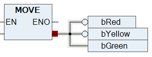
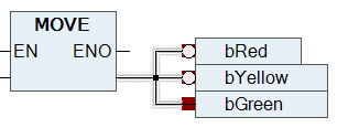
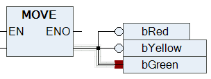
Drag and drop of a variable from the declaration part into the editor | Requirement: The respective element is selected in the declaration.
When a variable is dragged and dropped from the declaration part onto an existing replaceable element, the existing element is replaced. |
Drag and drop of a function block or programming block from the project tree or the Library Manager into the editor | A function block element with the corresponding type is inserted.
|
Rearranging the order of inputs and outputs within a function block using drag and drop. | Requirement: the text field of the input or output to be reordered to another position is selected. |
[Ctrl] + click in the programming area | Requirement: an element is selected in the Toolbox view. As long as you hold down [Ctrl] , a selected element is created each time you click in the programming area. |
[Ctrl] + right arrow | Requirement: in the CFC program, exactly one output pin is selected for an element. The selection is moved so that the input pin is selected at the end of the connecting line. If there are several pins, all of them are selected. Sample:
|
[Ctrl] + left arrow | Requirement: in the CFC program, exactly one input pin is selected for an element. The selection is moved so that the output pin at the beginning of the connecting line is selected. If there are several pins, all of them are selected. Sample:
|

See also:
Connect
You can insert connecting lines between element pins. Connecting lines are inserted with auto-routing so that they are automatically optimal and as short as possible. The connecting lines are checked for collisions.
Drag-and-drop from one pin to another | A connecting line is inserted between the 2 element pins. |
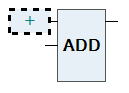
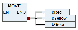
Drag-and-drop from a pin to a function block | Drop can be performed on a pin or on the text field of a connection. For extensible operators (for example ADD) the drop can also be done within the function block. The following behavior applies: If there are still unconnected input pins, the uppermost free pin is connected. If there are no more unconnected input pins, then a new pin is automatically inserted at the bottom. |
Command Connect selected pins | Requirement: you have selected several pins. The pins are marked in red. |
Move inserted element so that it touches the pin of another element. | Requirement: option Enable AutoConnect is enabled. The touching pins are automatically connected to each other. |
| The connection icon is located in the upper right corner in the editor. A green icon indicates collision-free connections. A red icon indicates collisions. Clicking on the icon opens a menu with commands for collision processing, for example the command Show next collision. |
| Requirement: you have selected a connection and the command Connection mark. Instead of a long connecting line, a connection is represented by connection marks. |

See also:
See also: