Programming in CFC
You can wire programming blocks together in the CFC Editor and create descriptive block diagrams.
The editor supports you as follows:
- Programming with elements and connecting lines
- Dragging instances and variables to the editing area
- Auto-routing of the connecting lines
- Automatic connecting
- Fixing connecting lines by control points
- Collision detection
- Input support for connection marks
- Forcing and writing values in online mode
- Moving the selection using arrow keys
- Reduced representation of a function block without unconnected connections
Creating a POU in the implementation language Continuous Function Chart (CFC)
- 1. Select a folder in the Solution Explorer in the PLC project tree.
- 2. In the context menu select the command Add > POU...
- The Add POU dialog opens.
- 3. Enter a name and select the implementation language Continuous Function Chart (CFC).
- 4. Click Open.
- TwinCAT adds the POU to the PLC project tree and opens it in the editor.
Insert elements and interconnect them with connecting lines
- 1. Position a Function block element and an Output element in the editor. Use the mouse to drag the elements from the Toolbox view into the editor.
- 2. Click on the output of the Function block element.
- The output is marked with a red square.
- 3. With the mouse button pressed, draw a connecting line from the output of the Function block element to the input of the Output element.
- When the input pin is reached, the cursor changes its symbol.
- 4. Release the mouse button.
- The output pin of the function block is connected to the input pin of the output.
Alternatively, you can select the two pins while pressing the [Ctrl] key, followed by selecting the command Connect Selected Pins in the CFC menu or the context menu.
Call instances
- 1. Create a new project and add a default PLC project
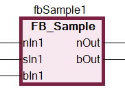
- 2. Create the function block FB_Sample in the implementation language ST with inputs and outputs:
FUNCTION_BLOCK FB_Sample
VAR_INPUT
    nIn1 : INT;
    nIn2 : INT;
    sIn1 : STRING := 'Name';
    bIn1 : BOOL;
END_VAR
VAR_OUTPUT
    nOut : INT;
    sOut : STRING;
    bOut : BOOL;
END_VAR
VAR
END_VAR
nOut := nIn1 + nIn2;
sResult := sIn1;
IF bIn1 THEN
bOut := TRUE;
END_IF- 3. Create the program PRG_First in the implementation language ST .
- 4. Instantiate function blocks and declare variables:
PROGRAM PRG_First
VAR
    nCounter  : INT;
    fbSample1 : FB_Sample;
    fbSample2 : FB_Sample;
    nResult   : INT;
    sResult   : STRING;
    bResult   : BOOL;
END_VAR- 5. Drag a Box element from the Toolbox view into the editor.
- 6. Click on the ??? field and type ADD.
- The function block type is ADD. The function block acts as an adder.
- 7. Click the line number 3 in the declaration editor.
- The declaration line of
nCounteris selected. - 8. Click in the selection and drag the selected variable into the implementation. Focus an input of the ADD function block there.
- An input was created, declared and connected to the function block.
- 9. Click again in the selection and drag the variable to the output of the ADD function block.
- An output was created, declared and connected to the function block.
- 10. Drag from the Toolbox view an Input element into the implementation.
- 11. Click on its field ??? and enter 1.
- 12. Connect input 1 to an input on the ADD function block.
- A network is programmed. At runtime, the network counts the cycles and stores the result in
nCounter.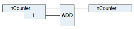
- 13. Click the line number 4 in the declaration editor.
- The line with fbSample1 is selected.
- 14. Click in the selection and drag the selected instance into the implementation.
- The instance appears as a function block in the editor. Type, name and the function block pins are displayed accordingly.
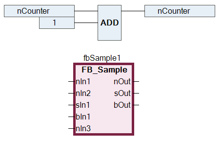
- 15. Drag the fbSample2 instance into the editor. Interconnect the instances with each other and with inputs and outputs.
- Sample:
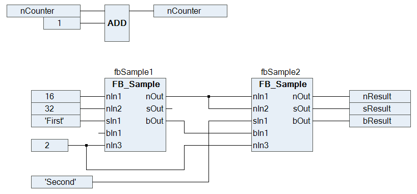
A program in ST with the same functionality could look like this:
PROGRAM PRG_First_ST
VAR
    nCounter  : INT;
    fbSample1 : FB_Sample;
    fbSample2 : FB_Sample;
    nResult   : INT;
    sResult   : STRING;
    bResult   : BOOL;
END_VAR
nCounter := nCounter + 1;
fbSample1(nIn1 := 16, nIn2 := 32, sIn1 := 'First', xItem := TRUE, nIn3 := 2, nOut => fbSample2.nIn1, bOut => fbSample2.bIn1);
fbSample2(nIn2 := fbSample1.nOut, sIn1 := 'Second', nIn3 := 2, nOut => nResult, sOut => sResult, bOut => bResult);Creating connection marks
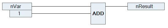
- You have a CFC programming block with connected elements.
- 1. Select a connecting line between two elements.
- The connecting line is selected, and the input or output of the elements is marked with a red square
 .
.
- 2. Select the command Connection Mark in the context menu or the CFC menu.
- The connection is disconnected and replaced with a connection mark - source and a connection mark - sink. The mark name is generated automatically.
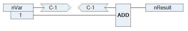
- 3. Click in the connection mark source.
- The name can be edited.
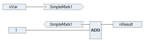
- 4. Enter a name for the source connection mark.
- Source connection mark and sink connection mark have the same name.
See also:
Resolving collisions and fixing connecting lines by control points
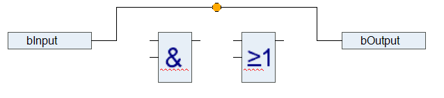
The following example illustrates the application if the command Route All Connections, and the application of control points.
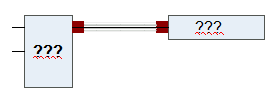
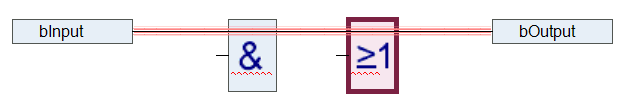
- 1. Position the elements input and output and link the elements.

- 2. Position two function block elements on the line.
- The connecting line and the function blocks are shown in red due to the collision.
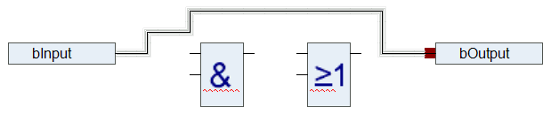
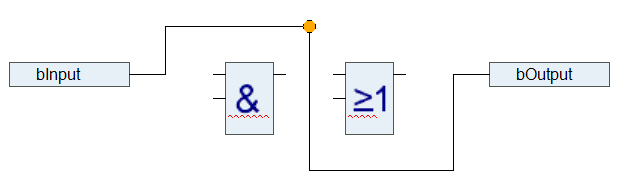
- 3. Select the command Route All Connections in the CFC > Routing menu.
- The collision is resolved.
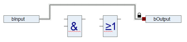
- 4. Change the connecting lines step by step.
- The connecting line was changed manually and is now locked for auto-routing. This is indicated by a padlock at the end of the connection.
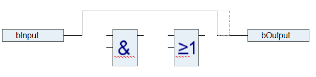
- 5. Select the connecting line and select the command Create Control Point in the CFC > Routing menu. Alternatively, you can drag a control point from the Toolbox view onto a line.
- A control point is created on the connecting line. The connecting line is fixed at the control point.
- 6. Change the connection according to the example below.
- The control point enables you to modify the connecting line as required. You can set as many control points as you want.
- 7. Remove the control point with the command Remove Control Point in the CFC > Routing menu.
- 8. Unlock the connection with the command Unlock Connection or by clicking on the padlock symbol.
- 9. Select the connecting line and select the command Route All Connections.
- The connecting line is drawn automatically, as shown under step 3.

 | Connections within a group are not automatically routed. |
See also:
Reduce representation of a function block
Requirement: a CFC programming block is open. In the editor, its function blocks are displayed with all declared connections.
- 1. Select a function block whose connections are partially unconnected.
- Example: FB_Sample
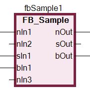
- The function block requires space for all connections.
- 2. From the menu CFC > Routing, select Remove Unused Pins.
- The function block requires less space and is now only displayed with the functionally relevant connections.