Automatic execution order by data flow
The execution order in programming blocks is uniquely determined in text-based and network-based editors. In the CFC editor, however, you can position the elements freely, so the execution order is initially not unique. It is therefore determined by TwinCAT according to the data flow and, in the case of multiple networks, according to the topological position of the elements. The elements are sorted from top to bottom and left to right. The programming block is thus processed while optimized by time and by cycle.
You can get information about the time sequence of the elements in the chart and briefly display the execution order. When you program networks with feedback, you can define an element as the starting point in the feedback loop.
You can also explicitly edit the processing order in a CFC object if necessary. To do this, change the value of the Explicit Execution Order property from the default False to True. In the Explicit Execution Order mode you have the possibility to edit the execution order with menu commands.
Data flow
The chronological sequence of which data is read or written when and how in which programming objects is generally referred to as data flow. A programming block can process any number of data flows, which can also be executed independently of each other.
Displaying execution order
In the automatic data flow mode, which is activated by default, the execution order of a CFC object is determined automatically. You can have the execution order briefly displayed in the CFC editor.
- 1. Create a new project and add a default PLC project.
- 2. Create the function block
FB_Samplein the ST implementation language with inputs and outputs.
FUNCTION_BLOCK FB_Sample
VAR_INPUT
    nIn1 : INT;
    nIn2 : INT;
    sIn1 : STRING := 'Name';
    bIn1 : BOOL;
END_VAR
VAR_OUTPUT
    nOut : INT;
    sOut : STRING;
    bOut : BOOL;
END_VAR
VAR
END_VAR
nOut := nIn1 + nIn2;
sResult := sIn1;
IF bIn1 THEN
bOut := TRUE;
END_IF- 3. Create the Execute_CFC program in the CFC implementation language.
PROGRAM Execute_CFC
VAR
    fbSample1 : FB_Sample;
    fbSample2 : FB_Sample;
    nResult1  : INT;
    nResult2  : INT;
    bResult   : BOOL;
END_VAR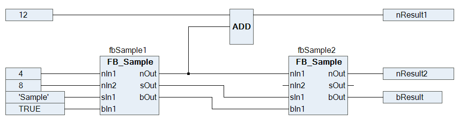
Newly created programming objects in CFC have the automatic data flow mode activated. The execution order of the programming object is optimally defined internally.
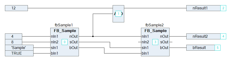
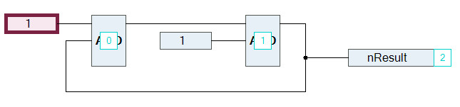
- 4. Select the command Execution Order > Display Execution Order in the CFC menu.
- The execution order of the object is shown. The boxes and outputs are numbered accordingly and reflect the chronological processing order. As soon as you click again in the CFC editor, the numbering will be hidden.
Determining execution order in feedback networks
- 1. Create a CFC program with feedback.
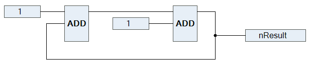
- 2. Select an element within the feedback.
- The selected element is highlighted in red.
- 3. Select the command Execution Order > Set Start of Feedback in the menu CFC.
- At runtime, this function block is processed first. The start function block of the feedback is defined and decorated with the
 symbol. The execution order is reordered and the selected element gets the number 0 (generally the lowest number in the feedback).
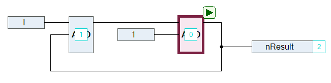
- 4. Select the start function block again.
- 5. Select the command Execution Order > Set Start of Feedback in the menu CFC.
- 6. The function block is deselected as start function block. The execution order is defined internally.
- 7. Select the command Execution Order > Display Execution Order in the CFC menu.
- The execution order by data flow is displayed.
Defining the execution order explicitly
The automatically defined execution order by data flow results in time and cycle optimized execution of the programming block. Thus, you do not need any information about the internally managed execution order during the development process.
In the Explicit Execution Order mode, you adjust the execution order on your own responsibility and have to assess the consequences and effects yourself. This is another reason why the execution order is always displayed.
You can explicitly change the automatically defined execution order of a CFC object if you have enabled the Explicit Execution Order property.
- 1. Select a CFC object in the project tree.
- 2. In the context menu, click Properties.
- 3. Set the Explicit Execution Order option under CFC to True.
- The Explicit Execution Order mode is enabled. In the CFC editor, the networks are numbered. Various commands for editing the execution order are available at Execution order in the CFC menu.
- 4. Open the CFC object.
- 5. Select a numbered element and select the command Execution Order > Move to Beginning.
- The execution order is resorted and the selected element has the number 0.
See also: