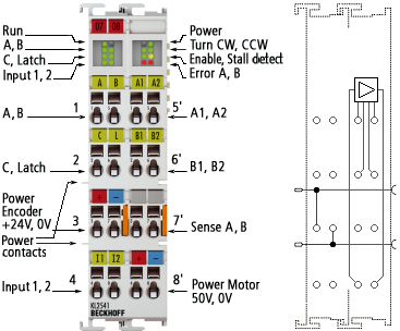
KL2541 - Connection
 WARNING
Bring the Bus Terminals system into a safe, de-energized state before starting mounting, disassembly or wiring of the Bus Terminals.
Terminal points - left part of the housing
Terminal point | No. | Connection |
|---|---|---|
A | 1 | Encoder input A |
C | 2 | Encoder input C (zero input). If bit CW.0 is set in the control word and a rising edge occurs at encoder input C, the current counter value is stored as a reference mark in the latch register. |
Encoder supply + | 3 | KL2541-0000: 24 V Encoder supply (from positive power contact) |
Input 1 | 4 | Digital input 1 (24 VDC). The current counter value is saved as a reference mark in the latch register if bit CW.1 is set in the control word and a rising edge occurs at digital input 1. |
B | 5 | Encoder input B |
Latch/Gate | 6 | Latch input. The current counter value is stored as a reference mark in the latch register, if in the control word
The counter can be disabled via this input if
If the counter is disabled, this is reported from the terminal to the controller via status bit SW.7. |
Encoder supply 0 V | 7 | Encoder supply (from negative power contact) |
Input 2 | 8 | Digital input 2 (24 VDC). The current counter value is saved as a reference mark in the latch register if bit CW.2 is set in the control word and a rising edge occurs at digital input 2. |
Terminal points - right part of the housing
Terminal point | No. | Connection for |
|---|---|---|
A1 | 1' | Motor winding A |
B1 | 2' | Motor winding B |
Sense A | 3' | Motor winding A |
Motor supply | 4' | Supply for output stages (maximum +50 VDC) |
A2 | 5' | Motor winding A |
B2 | 6' | Motor winding B |
Sense B | 7' | Motor winding B |
Motor supply | 8' | Supply for output stages (0 VDC) |
 | Connection examples Note the connection examples for the KL2541. |
Power contacts
The power contacts (+24 VDC) supply the following consumers:
- Incremental encoder (terminal points 3 and 7)
- Digital inputs (terminal points 4 and 8)
- Output driver of the stepper motor terminal
| Order of switch-on of the supply voltages When the K-bus voltage is switched on, the power contacts must already be energized, so that internal circuits (output drivers) can be initialized. If this is not possible (e.g. because the supply is activated via the emergency off circuit), a software reset is required for the terminal, once the system has started up (see command 0x8000). |
WARNINGIf the K-bus voltage (5 V) fails, the motor controller is not reset! In other words, if the motor is in motion, it is not stopped!