IO Data Assignment of IL230x and Extension Boxes
Digital Signals
(bit-oriented)
The digital Signals are bit-oriented. This means that one bit in the process image is assigned to each channel. The ILxxxx-B520 creates a memory area containing the current input bits and ensures that the bits in a second memory area dedicated to the output channels are written out immediately.
Analog Signals
(byte-oriented)
The processing of analog signals is always byte-oriented. Analog input and output values are represented in memory by two bytes each. Values are represented in unsigned/signed integer or two’s complement format (see IExxxx manual). The number “0” stands for the input/output value “0 V”, “0 mA” or “4 mA”. Per default, Control and Status Bytes for each analog channel are not mapped to the IO-data image. An analog channel is represented in the process image by two bytes.
Special Signals and interfaces
(byte-oriented)
The ILxxxx-B520 supports extension boxes with other interfaces such as RS232, RS485 incremental encoder, SSI Sensor interface. These signals can considered similarly to the analog signals named above. For some special signals the width of 16 Bit is not sufficient. The IL230x can Support any byte width.
Assignment of inputs/ outputs to the process image
(Default Assignment / Assembly Object)
Once it has been switched on, the ILxxxx-B520 finds out how many Extension Boxes are connected and creates an assignment list. The analog and digital channels, divided into inputs and outputs, are assembled into different parts of the list. The assignment starts on the first extension box next to the ILxxxx-B520. The software in the ILxxxx-B520 collects the individual entries for each of the channels in order to create the assignment list.
IO Data from Master / Scanner to ILxxxx-B520
(Default Assignment / Assembly Object)
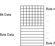
IO-Data which is transferred from the DeviceNet Master / Scanner to the ILxxxx-B520 begins with byte-oriented values which is the data for the analog output and special signal extension boxes. The bit-oriented data for the digital outputs of the ILxxxx-B520 and the digital output extension boxes is transmitted after the byte-oriented data. If the total number of digital inputs is not a multiple of 8, there will be a number of bits left over in the last data byte. These will be discarded.
IO Data from ILxxxx-B520 to Master / Scanner to
(Default Assignment / Assembly Object)
IO-Data which is transferred from the ILxxxx-B520 to the DeviceNet Master / Scanner begins with byte-oriented values which is the data from the analog input and special signal extension boxes. The bit-oriented data for the digital inputs of the ILxxxx-B520 and the digital input extension boxes is transmitted after the byte-oriented data. If the total number of digital outputs is not a multiple of 8, there will be a number of bits left over in the last data byte. These will be discarded.
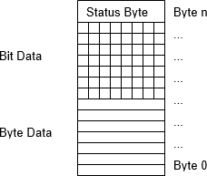
Status Byte at the end of the input data
An extra status byte is transferred at the end of the Input Data and returns the status of the ILxxxx-B520 with the following meaning:
- Bit0: IL_Error : IO Error, internal Data exchange ILxxxx-B520 has failed
- Bit1: IL-Cfg : ILxxxx-B520 Configuration Error
- Bit2: reserved
- Bit3: Diag : Diagnosis of analog Channel
- Bit4: reserved
- Bit5: reserved
- Bit6: reserved
- Bit7: FB_Error : Fieldbus Error / Idle Mode
The status byte corresponds to the Attribute “IL-Status” of the IL-Config Object.
IO Data from Master / Scanner to ILxxxx-B520 | IO Data from ILxxxx-B520 to Master / Scanner |
|
|