Basic function principles
 | RMS value (rms) specifications All AC value specifications in this documentation such as RMS specifications (rms) refer to a 50/60 Hz 3-phase mains network with a sinusoidal waveform. |
Introduction
The EL3783 has 6 analog input channels which are measured simultaneously in their respective measuring ranges. The 3 analog input channels for current measurement have different measuring ranges. These can be set via CoE or selected automatically by the EL3783 on the basis of the momentary measured values.
Each channel has an anti-aliasing low-pass filter with a limit frequency of 5.5 KHz. However, the high sampling rate of 20 KSps also allows frequency components up to higher than 9 KHz to be detected.
Further information is available upon request.
| Using the sample programs This document contains sample applications of our products for certain areas of application. The application notes provided here are based on typical features of our products and only serve as examples. The notes contained in this document explicitly do not refer to specific applications. The customer is therefore responsible for assessing and deciding whether the product is suitable for a particular application. We accept no responsibility for the completeness and correctness of the source code contained in this document. We reserve the right to modify the content of this document at any time and accept no responsibility for errors and missing information. |
Automatic current range switching
The EL3783 features automatic current range switching. This can be configured via the sub-indices in object 0xF80D.
During a switching event, processes within the terminal lead to measured data lying outside the specified accuracy for about 250 µs. This short-term inaccuracy is signaled to the PLC via Object 0xF603. Depending on the application there must be a reaction to this on the software side.
In order to use this function, it must be activated via the CoE object "0xF80D:11 Current range" and configured as desired. Various dynamics are pre-programmed according to which the switching takes place quickly (Dynamic 0) or slowly (Dynamic 3).
The following sample project (see appendix) shows amongst other things how a conversion of the PDO values can be carried out, including automatic range switching.
Sample program (download)
Declaration of variables and source code:
               „
EL3783_HCBorderCnt := 0;
EL3783_5ARange := FALSE;
CF := 1.8415054;

FOR i:= 0 TO 19 DO

                IF i = EL3783_HCRange[EL3783_HCBorderCnt] THEN
                               EL3783_5ARange := NOT EL3783_5ARange;
                               IF EL3783_5ARange THEN
                                               CF := 9.207527;
                               ELSE
                                               CF := 1.8415054;
                               END_IF
                               EL3783_HCBorderCnt := EL3783_HCBorderCnt + 1;
                END_IF

                EL3783_UL1_DC20[i] := INT_TO_LREAL(EL3783_UL1_DC_020[i])
* 737.2575 / 32768;
                EL3783_UL2_DC20[i] := INT_TO_LREAL(EL3783_UL2_DC_020[i])
* 737.2575 / 32768;
                EL3783_UL3_DC20[i] := INT_TO_LREAL(EL3783_UL3_DC_020[i])
* 737.2575 / 32768;

                EL3783_IL1_DC20[i] := INT_TO_LREAL(EL3783_IL1_DC_020[i])
* CF / 32768;
                EL3783_IL2_DC20[i] := INT_TO_LREAL(EL3783_IL2_DC_020[i])
* CF / 32768;
                EL3783_IL3_DC20[i] := INT_TO_LREAL(EL3783_IL3_DC_020[i])
* CF / 32768;

END_FOR
               „
Preparations for starting the sample programs (tnzip file / TwinCAT 3)
- Click on the download button to save the Zip archive locally on your hard disk, then unzip the *.tnzip archive file in a temporary folder.
- Select the .tnzip file (sample program).
- A further selection window opens. Select the destination directory for storing the project.
- For a description of the general PLC commissioning procedure and starting the program please refer to the terminal documentation or the EtherCAT system documentation.
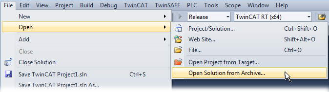 Fig.144: Opening the *. tnzip archive
- The EtherCAT device of the example should usually be declared your present system. After selection of the EtherCAT device in the “Solutionexplorer” select the “Adapter” tab and click on “Search...”:
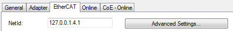
- Checking NetId: the “EtherCAT” tab of the EtherCAT device shows the configured NetId:
 .
.
The first four numbers must be identical with the project NetId of the target system. The project NetId can be viewed within the TwinCAT environment above, where a pull down menu can be opened to choose a target system (by clicking right in the text field). The number blocks are placed in brackets there next to each computer name of a target system. - Modify the NetId: By right clicking on “EtherCAT device” within the solution explorer a context menu opens where “Change NetId...” have to be selected. The first four numbers of the NetId of the target computer must be entered; both last values are 4.1 usually.
Example: - NetId of project: myComputer (123.45.67.89.1.1)
- Entry via „Change NetId...“: 123.45.67.89.4.1
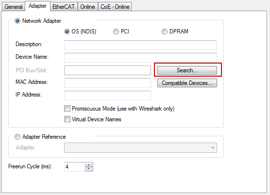 Fig.145: Search of the existing HW configuration for the EtherCAT configuration of the example
Measuring ranges 1 A, 5 A
Fixed current ranges up to 1.3 times the respective rated value for sinusoidal currents. The 1 A range is the default value on delivery from the factory.
DYN 0
By default the terminal is in the 1 A current measuring range. The terminal switches over to the 5 A measuring range as soon as the current in one of the three channels exceeds the permanently coded threshold value T1A→5A of approx. 1.74 A (momentary). The switchover takes 250 µs at the most. Switching back takes place as soon as the maximum values of a full half-wave on all the current channels lie below the threshold value T_(5A→1A) of approx. 1.69 A (momentary).
DYN1, DYN2, DYN3
By default the terminal is in the 1 A current measuring range. The terminal determines the maximum value of the current separately for each half-wave and each current channel. The determined maximum values  for each half-wave are averaged channel-by-channel with an exponential filter of the form.

The terminal switches over to the 5 A measuring range as soon as the filtered value  exceeds the threshold value
  . The difference between the characteristics for the switchover is due to the choice of the respective coefficients
  . The coefficient is formed by
  , where
  is the constant from the name of the setting ("DYN "). In turn, it follows that the setting variant DYN 3 requires more half-waves exceeding the threshold value in order to switch over than a smaller setting such as DYN 1.
Switching from the 5 A measuring range back to the 1 A measuring range takes place analogously with the aid of the filter. Switching back takes place as soon as the average of the maximum values of all the current channels lies below the threshold value  .
.
The settings DYN1, DYN2 and DYN3 are intended for current measurements in grids in which temporary current peaks occur. However, these peaks should not cause any direct switchover of the terminal. If there should be an error that results in a lengthy fault current, however, the terminal will switch over.
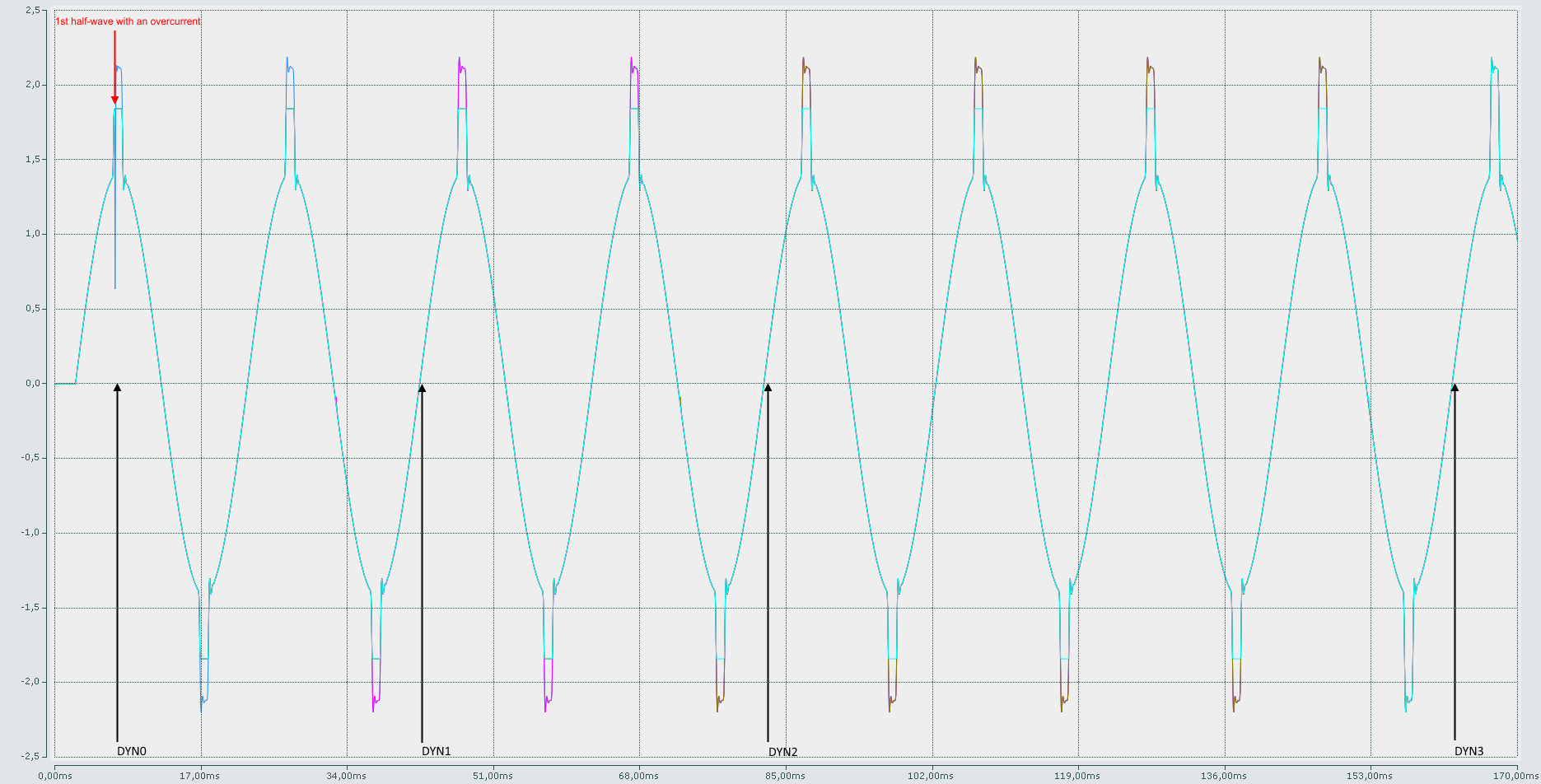 Fig.146: Switchover characteristic, DYN0 - DYN3
Rated voltages, list of grids
The tables below show suitable rated grid voltages according to EN60664-1:2003 for the voltage measuring inputs of the EL3783
three-phase, 4-conductor grid with earthed protective conductor | |
|---|---|
UL-N | UL-L |
66 V | 115 V |
120 V | 208 V |
127 V | 220 V |
220 V | 380 V |
230 V | 400 V |
240 V | 415 V |
260 V | 440 V |
277 V | 480 V |
347 V | 600 V |
400 V* | 690 V* |
*) maximum rated voltage of the grid
three-phase, 3-conductor grid, not earthed |
|---|
UL-L |
66 V |
115 V |
120 V |
127 V |
200 V |
220 V |
230 V |
240 V |
260 V |
277 V |
347 V |
380 V |
400 V |
415 V |
440 V |
480 V |
500 V |
577 V |
600 V* |
*) maximum rated voltage of the grid
| Technical data All technical specifications apply to "3-phase, 4-conductor system with earthed neutral conductor" unless explicitly stated otherwise (see also Examples of measurement methods). |
| Changes in the CoE directory In case of changes to the CoE default parameters, it is essential that corresponding values are entered in the start-up list, so that in the case of exchange the EL3783 operates again as foreseen in the application. |