LEDs and connection
| |
Do not operate current transformers in no-load mode! Please note that many manufacturers do not permit their current transformers to be operated in no-load mode! Connect the EL3783 to the secondary windings of the current transformers before using the current transformer! |

| |
Earthing of the terminal point N when measuring current! If you do not connect the terminal point N with the neutral conductor of your mains supply (e.g. if the EL3783 is used purely for current measurements), terminal point N should be earthed, in order to avoid dangerous overvoltages in the event of a current transformer fault! |
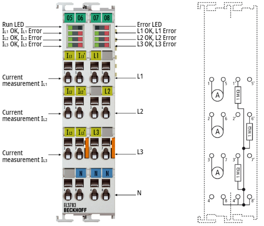 Fig.4: EL3783 (Component values only exemplary, exact value s. Technical data)
Left side | Right side | ||||
|---|---|---|---|---|---|
Terminal point | Description | Terminal point | Description | ||
Name | No. | Name | No. | ||
IL1 | 1 | Phase L1 current measurement input | L1 | 1' | Phase L1 voltage measurement input |
IL2 | 2 | Phase L2 current measurement input |
| 2' | n.c. |
IL3 | 3 | Phase L3 current measurement input | L3 | 3' | Phase L3 voltage measurement input |
| 4 | n.c. | N | 4' | Neutral conductor |
IL1' | 5 | Phase L1 current measurement output |
| 5' | n.c. |
IL2' | 6 | Phase L2 current measurement output | L2 | 6' | Phase L2 voltage measurement input |
IL3' | 7 | Phase L3 current measurement output |
| 7' | n.c. |
N | 8 | Neutral conductor | N | 8' | Neutral conductor |
LEDs
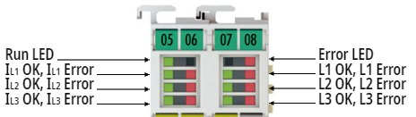 Fig.6: EL3783 LEDs
LED | Color | Meaning | |
|---|---|---|---|
RUN | green | This LED indicates the terminal's operating state: | |
off | State of the EtherCAT State Machine: INIT = initialization of the terminal or BOOTSTRAP = function for firmware updates of the terminal | ||
flashing | State of the EtherCAT State Machine: PREOP = function for mailbox communication and different standard-settings set | ||
Single flash | State of the EtherCAT State Machine: SAFEOP = verification of the Sync Manager channels and the distributed clocks. | ||
on | State of the EtherCAT State Machine: OP = normal operating state; mailbox and process data communication is possible | ||
IL1 OK | green | on | Current IL1 ok |
IL1 Error | red | on | Overcurrent on L1. |
IL2 OK | green | on | Current IL2 ok |
IL2 Error | red | on | Overcurrent on L2. |
IL3 OK | green | on | Current IL3 ok |
IL3 Error | red | on | Overcurrent on L3. |
L1 OK | green | on | Voltage on L1 OK |
L1 Error | red | on | Overvoltage on L1. Voltage > 737 V (L1-N) |
L2 OK | green | on | Voltage on L2 OK |
L2 error | red | on | Overvoltage on L2. Voltage > 737 V (L2-N) |
L3 OK | green | on | Voltage on L3 OK |
L3 error | red | on | Overvoltage on L3. Voltage > 737 V (L3-N) |
Error | red | on | Other errors (logical OR conjuction) |
Wiring and measurement methods
Examples of wiring for measurements in the three-phase grid
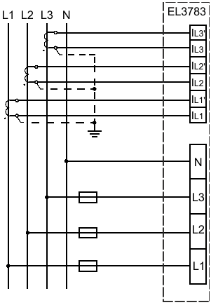 Fig.7: Measurement in a 3-phase, 4-conductor grid, asymmetrical load
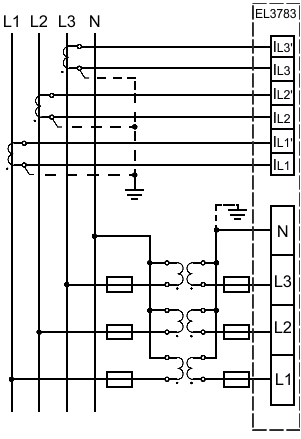 Fig.8: Measurement in a 3-phase, 4-conductor grid with 3 voltage transformers, asymmetrical load
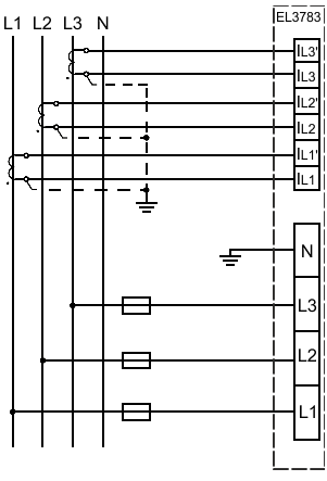 Fig.9: Measurement in a 3-phase, 3-conductor grid, asymmetrical load
| |
Risk of device damage! The user must ensure proper fusing of the voltage measurement path in accordance with the measured variable as well as adequate transient protection! |