Quick start
No special measures are required for the initial commissioning of the EL3255.
1. Mounting
Install the EL3255 as described in section Mounting and wiring.
Connect 1 - 5 potentiometers according to the pin assignment.
2. Configuration
Create a configuration in the TwinCAT System Manager by manually inserting the terminal or scanning it online. Refer to installation chapter TwinCAT 2.x regarding this.
 | EtherCAT XML Device Description If the XML description of the EL3255 is not available in your system you can download the latest XML file from the download area of the Beckhoff website and install it according to the installation instructions. |
3. Online operation
Activate the EtherCAT master and start the terminal in OP state. In the input variables the EL3255 must deliver State=OP (8) and WC=0.
4. Delivery state
The terminal behaves as follows in the delivery state or after scanning in the System Manager:
- 5 channels active
- 10 kOhm potentiometer (CoE setting 0x80n0:1C)
- Distributed Clocks deactivated, frame-triggered operation
- Filter deactivated
- Vendor calibration active
This results in a conversion time of typically 500 µs across all channels.
- Process data status + value for each channel
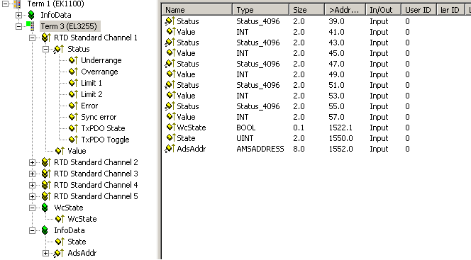 Fig.26: Default process data
|
Sensor position |
PDO-value | |
|---|---|---|
|
0 % |
x0000 |
0 |
|
50 % |
x3FFF |
16383 |
|
100 % |
x7FFF |
32767 |
- CoE settings (in this case channel 1: index x80n0, where n=0)
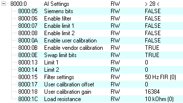 Fig.27: default CoE parameters
5. Distributed Clocks mode
If you wish to use Distributed Clocks mode, change the process data and the mode of operation accordingly.
Since the EL3255 is a device for input data, "DC-Synchron (input based)" is recommended.
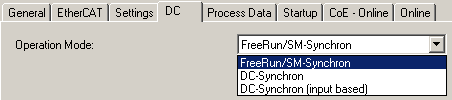 Fig.28: Distributed Clocks operating mode
The scanning of the potentiometers is then cyclically initiated by the DC-Sync signal; hence, synchronized operation with other DC-capable terminals can take place.
| Distributed Clocks and filters The activation of the filters is not permissible in Distributed Clocks mode. |
6. Setting the parameters and process data
Process data
Via the PDO selection, 5 - 1 channels can be selected as PDOs to be cyclically transmitted (A). The deactivation of a channel reduces the size of the process image; the corresponding Error LED then no longer has any function.
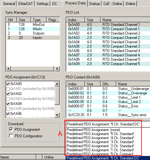 Fig.29: PDO selection
CoE parameters
The CoE parameters can now be changed for each channel in the CoE.
| Parameterization via the CoE list (CAN over EtherCAT) The terminal is parameterized via the CoE - Online tab (double-click on the respective object) or via the Process Data tab (allocation of PDOs). Please note the following general CoE information when using/manipulating the CoE parameters: - Keep a startup list if components have to be replaced - Differentiation between online/offline dictionary, existence of current XML description - Use "CoE reload" for resetting changes |
The following settings should be made in each channel
1. Nominal resistance of connected potentiometer
The electrical measuring range encompasses potentiometers from 300 Ω to 50 kΩ. An internal correction function improves the measuring accuracy by linearization if the connected potentiometer is known to the terminal.
Therefore the load resistance is to be set in the CoE x80n0:1c. The setting closest to the actual value is to be selected.
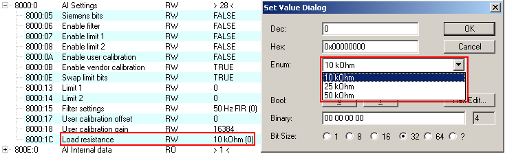 Fig.30: CoE, nominal resistance setting
 | Note on open-circuit recognition from firmware 04
|
2. Filter setting
The filter setting from channel 1 is simultaneously effective for all channels.
A combination of Distributed Clock mode and filter activation is not permissible.
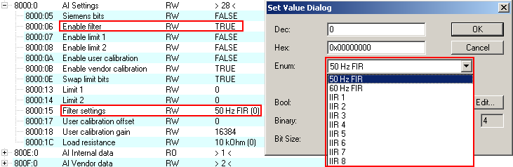 Fig.31: CoE, filter setting
With the exception of the filter setting, different values can be specified for each channel.
The settings can also be loaded via the SPS/PLC/Task at runtime, e.g. using function blocks from TcEtherCAT.lib.
7. Diagnostics
Both the terminal and each individual channel signal their proper function in status variables, see Process data.
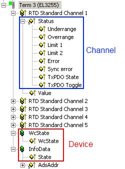 Fig.32: Process data for the diagnosis
For proper operation the cyclic evaluation of the following information is recommended:
- Device EL3255
- WorkingCounter WcState
must be 0 in each cycle, otherwise no valid data acceptance has taken place. - Status State
The EC status of the terminal must be in OP mode, i.e. the 3rd bit is set. There must not be any error. - per channel
- Error, Underrange, Overrange
These variables must be 0/FALSE. - SyncError
This variable indicates a synchronization error in DC mode and must be 0/FALSE. - TxPDO State
This variable indicates an internal process data error and must be 0/FALSE. - TxPDO Toggle
This variable indicates the delivery of new data by changing its value.
8. Operation
During operation the potentiometers/sensors are cyclically measured and the process value is transmitted to the master.