Process data
The process data overview lists the detailed PDO selection. These data are not usually necessary for operation under TwinCAT, since they can be simply configured from the configuration interface via the process data preselection.
Preselection of process data
An EtherCAT device usually offers several different process data objects (PDO) for input and output data, which can be configured in the System Manager, i.e. they can be activated or deactivated for cyclic transmission. See further below for the corresponding overview.
From TwinCAT 2.11 on, with the EtherCAT devices intended for the purpose according to the ESI/XML description, the process data for input and output can be activated simultaneously by appropriate predefined sentences, the so-called "predefined PDO".
In the "Process Data" tab, the EL3255 has
 Fig.149: “Process Data” tab
the following “predefined PDO” sentences (input data only):
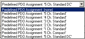 Fig.150: TwinCAT System Manager with the PDO selection
In detail the sentences are composed as follows:
|
Operating mode |
Name |
SM2, PDO assignment |
SM3, PDO assignment |
|---|---|---|---|
|
SM-synchron “frame-triggered” |
5 Ch. Standard (default setting) |
- |
0x1A00 |
|
|
4 Ch. Standard |
- |
0x1A00 |
|
|
3 Ch. Standard |
- |
0x1A00 |
|
|
2 Ch. Standard |
- |
0x1A00 |
|
|
1 Ch. Standard |
- |
0x1A00 |
|
|
5 Ch. Compact |
- |
0x1A01 |
|
DC-synchron |
5 Ch. Standard |
- |
0x1A00 |
Explanation of the process data
The default process image (5 Ch. Standard) encompasses the following data:
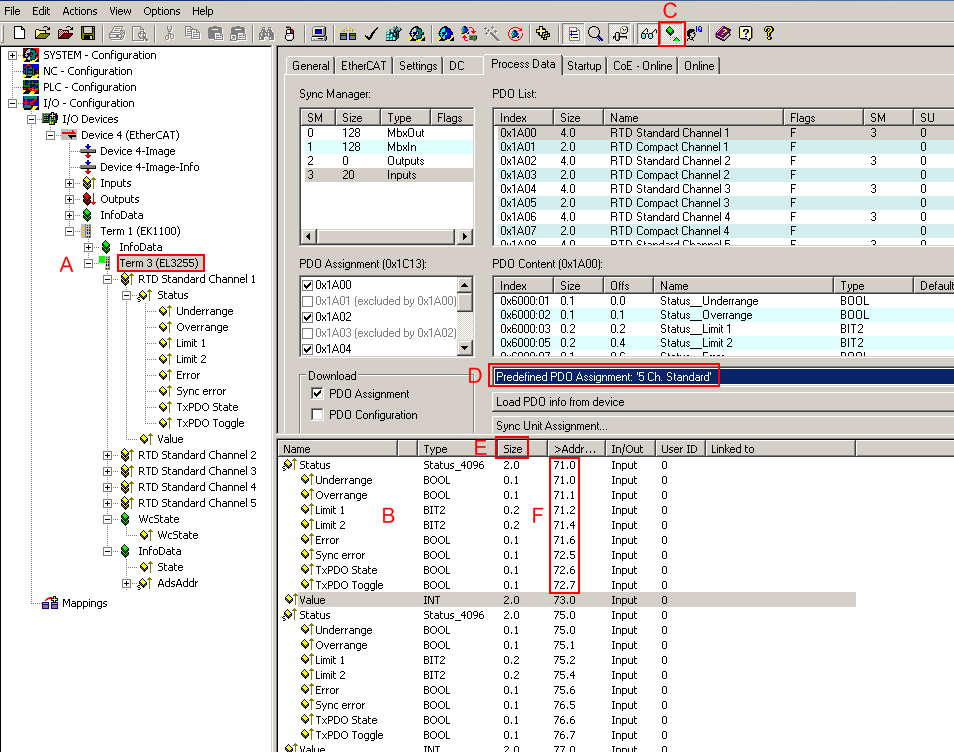 Fig.151: Standard EL3255 process image
The EL3255 (A) has 2-byte variables at its disposal with different bit meanings. These can be seen by expanding the tree (A). They are also displayed in the detail view (B) if the appropriate display function (C) is activated. Alternative process images can be set via the Predefined PDO (D).
The bit meaning i.e. offset position can then be taken from the memory assignment display (F) on the basis of the point notation, also taking into account the variable size (E). "71.2" means here that the 2nd bit (counting method 0,1,2, etc.) or 3rd bit (counting method 1,2,3, etc.) in the status word indicates the overrange. The user requires this information in the PLC if the status word is to be divided into its bit meanings.
Both the collective name e.g. Status and the individual bit variable e.g. Overrange can be linked, but not both at the same time.
|
Input data | |||
|---|---|---|---|
|
Collective name |
Name |
Description / function |
Bit position [0 - 15] |
|
Status |
Underrange |
Indicates that the electrical measuring range is undershot |
0 |
|
|
Overrange |
Indicates that the electrical measuring range is exceeded |
1 |
|
|
Limit 1 |
Evaluation limit 1 |
2 |
|
|
Limit 2 |
Evaluation limit 2, setting based on CoE object 0x80n0:08, see also Notes |
4 |
|
|
Error |
An error has occurred, |
66 |
|
|
Sync error |
Signals a synchronization error if “distributed clocks” are activated. |
13 |
|
|
TxPDO State |
Validity of the process data, TRUE means invalid process data on this channel |
14 |
|
|
TxPDO Toggle |
Changes its state 0/1 each time process data are exchanged. |
15 |
|
Value |
|
16-bit measured value 0 - x7FFF |
|
|
WcState |
|
Setpoint during operation: 0 Each datagram of the EL3255 indicates its processing state here. This allows the EL3255 to be monitored for correct process data communication. |
|
|
InfoData (State) |
|
Setpoint during operation: 8 Status display of the “EtherCAT state machine” |
|
|
AdsAddr |
|
AMS address of the responsible EtherCAT Master in the format "0.0.0.0.0.0". In addition, the port number valid for this Slave. |
|
Evaluation
For the regular operation of the EL3255 (as for every analog input terminal), proceed as follows via the diagnostic depth:
- Fieldbus/EtherCAT
- cyclic control of DevState
- Device/EL3255
- cyclic control of State, WcState
- Channel x
- cyclic control of Error, TxPDoState, SyncError (in case of DC operation)
If the "EL3255" device diagnostics signals no communication, then the subordinate "Channel" level is also no longer to be considered ready for operation.
Calculation of process data
The concept “calibration”, which has historical roots at Beckhoff, is used here even if it has nothing to do with the deviation statements of a calibration certificate. Actually, this is a description of the vendor or customer calibration data/adjustment data used by the device during operation in order to maintain the assured measuring accuracy.
The terminal constantly records measured values and saves the raw values from its A/D converter in the ADC raw value object 0x80nE:01. After each recording of the analog signal, the correction calculation takes place with the vendor and user calibration data as well as the user scaling, if these are activated (see following picture).
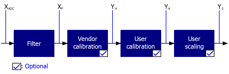 Fig.152: Calculation of process data
 Calculation | Designation |
|---|---|
XADC | Output of the A/D converter |
XF | Output value after the filter |
YH = (XADC – BH) x AH x 2-14 | Measured value after vendor calibration, |
YA = (YH – BA) x AA x 2 -14 | Measured value after vendor and user calibration |
YS= YA x AS x 2-16 + BS | Measured value following user scaling |
Name | Designation | Index |
|---|---|---|
XADC | Output value of the A/D converter | |
XF | Output value after the filter | - |
BH | Vendor calibration offset (not changeable) | |
AH | Vendor calibration gain (not changeable) | |
BA | User calibration offset (can be activated via index 0x80n0:0A) | |
AA | User calibration gain (can be activated via index 0x80n0:0A) | |
BS | User scaling offset (can be activated via index 0x80n0:01) | |
AS | User scaling gain (can be activated via index 0x80n0:01) | |
YS | Process data for controller | - |
 | Measurement result The accuracy of the result may be reduced if the measured value is smaller than 32767 / 4 due to one or more multiplications. |
Note about the 1-byte status of earlier EtherCAT terminals
Previous analog input terminals from Beckhoff (e.g. EL31x2) had a status byte instead of the status word that is now implemented and therefore a 3-byte interface. 8 additional bits now offer extended diagnostic options, wherein the default process image of the EL31xx now encompasses 4 bytes, status word and value word. The bit meanings of the LowByte are retained; Limit1 and Limit2 as 2-bit types are shown in the case of the EL31xx.
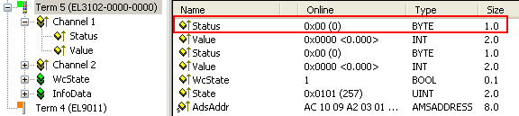 Fig.153: 3-byte interface of the EL31x2
If the 3-byte interface for linking to the analogue input channel is implemented in existing PLC projects, the TwinCAT System Manager nevertheless offers the possibility to link the EL31xx with a 4-byte interface.
To do this, open the link dialog as usual by double-clicking on the variable and activate the AllTypes checkbox. As a result, variables with differing sizes are also offered for linking. Select the corresponding 1-byte input variable for your application. The 8 bit coverage is confirmed in the following SizeMismatch dialog, Fig. Element-orientated process image under TwinCAT 2.10.
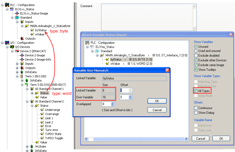 Fig.154: Connecting the 4-byte interface of the EL31xx to a 3-byte interface existing in the project