Application notes
 | Note on open-circuit recognition from firmware 04
|
Diagnostic options
The diagnostic functions of the terminal can be set via the CoE object 0x8047:11.
The settings apply to all channels together:
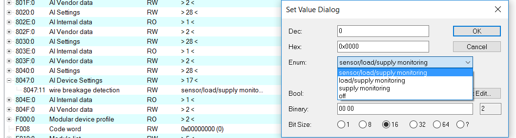 Fig.148: Set Value Dialog, diagnostic options
- Sensor Monitoring: Wiper wire break detection
- Load Monitoring: Monitoring of the potentiometer supply lines
- Supply monitoring: Monitoring of the 24 V supply via the power contacts, potentiometer overload/short circuit
It is recommended to use the full diagnostic scope if possible. If the terminal detects an error, Value=0 and Error=1 are reported.
In some cases it can happen that potentiometer wipers lose contact with the contact surface during movement, especially at higher speeds or increasing aging. In this case the wiper wire break detection can be switched off to avoid false alarms. Wiper wire break detection is performed by cyclic voltage pulses. The pulses can be measured from the outside (if the wiper is not grounded), but are not included in the measurement result of the channel.
Further characteristics
Feature | Explanation |
|---|---|
Potentiometer | The potentiometers connected to channels 1 - 5 do not have to be of the same type or resistance value. |
Power dissipation | Significant portions of power are converted into heat in the connected potentiometers. Due to the terminal feed of typically 10 V, approx. 0.3 W are converted in a 300 Ω potentiometer. |
Diagnostics | The Error LED or the status word indicates
A shunt between the wiper conductor and one end of the potentiometer feed cannot be recognized. See "Note on open-circuit recognition from firmware 04" |
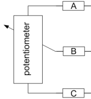
Compensation of supply cable resistances | In the case of very long cable lengths with small cross-sections the line resistances A and C can limit the measuring range. This error can be corrected with the "user calibration" function: To do this, activate the IIR 8 filter and the "Enable user calibration" function. Set the potentiometer to the lower limit and enter the input value in "User calibration offset". Then set the potentiometer to the upper limit and calculate the "User calibration gain": Y = 32768/X*16384.
|
Error Codes
Error | Underrange | Overrange | Data invalid | TxPDO State | Sync Error | Error description | Remedy |
|---|---|---|---|---|---|---|---|
1 | 1 |
|
|
|
| Measurement is below range | Reduce the input level, change the gain (filter settings) |
1 |
| 1 |
|
|
| Measuring range exceeded | Reduce the input level, change the gain (filter settings) |
1 |
|
|
|
|
| General measuring error | e.g. broken wire or short circuit |
|
|
|
|
| 1 | Synchronization error | Master jitter too high, DC switched off |
|
|
| 1 |
|
| Internal data error | Check data transmission |
|
|
|
| 1 |
| Internal data error | Check data transmission |