Current Sink PWM
 | Available from FW04 The operation mode described in this chapter for controlling an LED with an external supply can only be used from FW04 onwards. |
The operation mode “Current Sink PWM” is used when operating an LED with an external supply. This is the case, for example, with a multi-color Common Anode LED. The individual LEDs are supplied via the common anode. One EL2596 is required for each cathode (equivalent to “for each color”). These EL2596 terminals are then operated in “Current Sink PWM” mode.
In this operation mode, there are a few requirements to consider:
- The LED must not be connected to the EL2596 until the operation mode has been set. The LED is not connected between LED- (1) and LED+ (9) as in the other operation modes. The anode of the LED is connected to an external supply source and the cathode is connected to LED- (1) of the EL2596.
- The operation mode must not be changed while the LED is connected.
- The external supply of the LED may only be switched on after the terminal has started up. If this is not directly possible in the application, the supply must be connected via a relay terminal (EL2622, EL2624, ...).
- The same restrictions regarding the maximum duty cycle as described in the chapter on Current control PWM apply.
In this operation mode, it is possible to configure the trigger input as an enable input so that it can be used as an external switch. An output can then only be actuated with a prespecified signal at the trigger input. More detailed information and commissioning can be found in the chapter Hardware enable.
The commissioning of the “Current Sink PWM” mode is described step-by-step below.
- Nominal/limit current of the LED in index 0x8000:02 “Target current” in the unit mA
- Input voltage in index 0x8000:03 “Supply voltage” in the unit 0.01 V
- Desired output voltage in index 0x8000:04 “Output voltage” in the unit 0.01 V (max. UIN - 2 V). In this operation mode, the value set here corresponds to the output on the controller. If the forward voltage of the connected LED is lower than the value set here, the remaining voltage drops internally in the EL2596. In many cases, this leads to overtemperature in the terminal and thus to the switching off of the LED output. As the desired output voltage, therefore, the forward voltage at the desired output current should be set here. The TeachIn function can also be used to determine the output voltage (the LED must not be connected to the EL2596 when switching to the necessary operation mode).
- The default PWM frequency is 1050 Hz. If necessary, the value can be adjusted in index 0x8004:04.
WARNING
- Set the operation mode in the CoE directory in index 0x8004:01 to “Current Control PWM”
- The LED can now be connected.
- Set the predefined PDO assignments to “PWM (with info data)” or “PWM with current (and info data)”
- Only for Predefined PDO “PWM with current (and info data)”: Specify the set current in the unit mA via "DOX Current" → "Output Current"
- Specify “PWM duty cycle” under “DOX PWM duty” → “PWM duty”. If the PDO object 0x1604 “DOX PWM duty” is not mapped, the duty cycle is specified in the CoE index 0x8004:07.
- Check under “DOX Status” → “Status” whether the “Ready to activate” bit is 1
- Switch on the LED output under “DOX Control” → “Control” by activating the “Output” bit
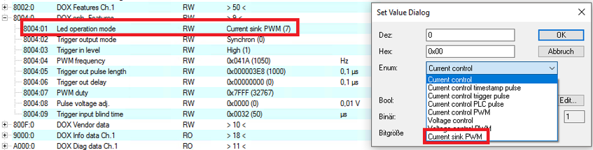 Fig.179: Operation mode setting “Current control PWM”
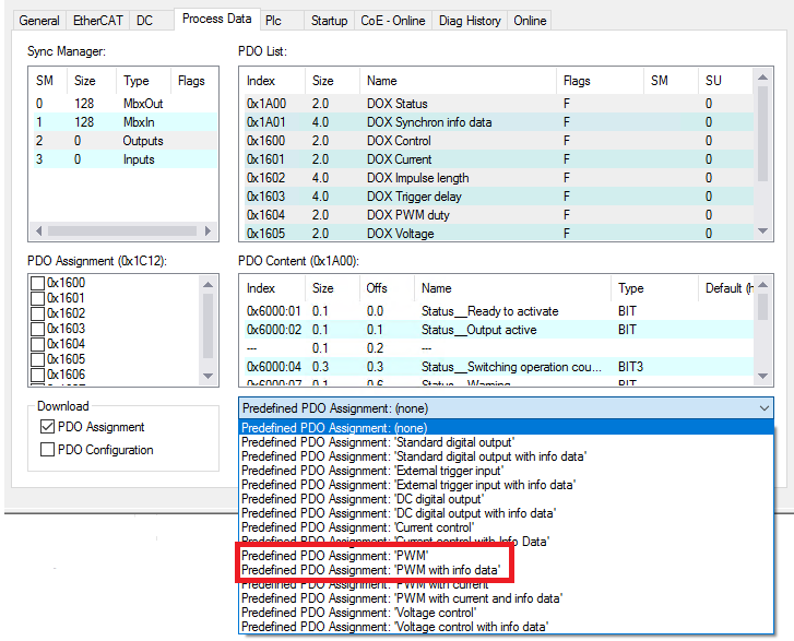 Fig.169: PDO setting “PWM (with info data)”
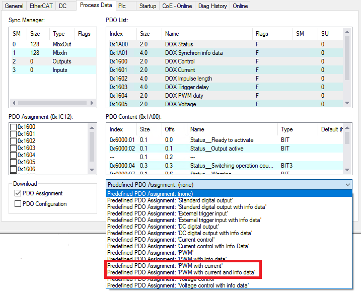 Fig.170: PDO setting “PWM with current (and info data)”
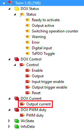 Fig.171: Setting the set current