Storage of the output voltage temporarily or in the EEPROM
Another way to determine and store the output voltage in the CoE index 0x8000:04 (temporarily or permanently) with a prespecified set current is the automatic determination. With this method, the LED is switched on with a prespecified set current and the output voltage is determined and saved in the CoE index 0x8000:04 “Output voltage”.
If a “TeachIn” is performed using the commands described in this chapter, the terminal is automatically operated in “Current control” mode for a short switching process until the set current is reached. This is independent of the actual set operation mode, which is reactivated afterwards. This is followed by a brief flash of the LED. Depending on the command, the value is then permanently stored in the EEPROM or only temporarily until the next startup. When storing the voltage value in the EEPROM, it must be borne in mind that only limited write access is possible to EEPROM memory cells.
After the specifying of the set current, the setting of the command and a rising edge on the output bit of the EL2596, the output voltage is determined. Since the LED does not need to be constantly switched on for this method and the determination is automatic after the command has been given, this method is fast. It is also suitable if the LED is to be overdriven with currents greater than the nominal current during operation. During the determination, the current is adjusted up to the specified set current, which is why the LED flashes for a short time. This method can therefore be used if the LED is to be operated later in a pulsed mode with overdriving at a current ≥ the nominal current.
Especially in the current controlled pulse operation modes the use of the automatic determination of the output voltage is recommended, because possibly for the generation of high current pulses at the output a high pre-voltage is needed to generate steep edges. These may be higher than voltages specified in the LED data sheet.
Notice | |
TeachIn in pulsed mode at operating temperature Automatic determination of the output voltage should be performed for all pulsing modes under operating conditions. Above all, the ambient temperature during teach-in is important and should correspond to the operating temperature. The reason for this is the decreasing forward resistance of the LED. If the resistance is reduced by rising temperatures at constant current at the LED output of the EL2596, less voltage drops across the LED than in the cold state. The voltage difference between the set output voltage and the voltage drop across the LED then drops internally in the terminal, causing the terminal to heat up. This can lead to the output being switched off due to overtemperature. If the teach-in is performed at operating temperature, internal losses can be avoided. For optimal parameterization, it is therefore recommended to perform two TeachIns. The first one in cold state to operate the LED first and to set it into operating conditions. The second TeachIn can then be performed under the achieved operating conditions. |
The function described in this chapter can be used in any current-controlled operation mode except “Current Sink PWM” (“Current Control”, “Current Control Timestamp pulse”, “Current Control PLC pulse”, “Current Control Trigger pulse”).
The procedure is described below:
- Specify the maximum output voltage in the CoE index 0x8000:04 “Output voltage” (especially if overdriving is desired, this value should be greater than the nominal voltage)
- Preset the set current in the process data under “DOX Current” → “Output Current”
- Specify the command to store the output voltage in the CoE index 0xFB00:01 “Request”
- 0x0502: permanent storage of the value in the EEPROM
- 0x0503: temporary storage of the value
- Apply a rising edge on ”DOX Control” → “Control” → “Output” (the enable bit “DOX Control” → “Control” → “Enable” must remain 0). The output is then adjusted up to the set current and switched off when the set current is reached, then the output voltage is stored.
- After successful determination, the status of the command in the CoE index 0xFB00:02 “Status" is 0xFF and “DOX Control” → “Control” → “Switching operation counter” is incremented. The stored voltage is then entered in the CoE index 0x8000:04 “Output voltage”.
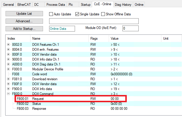 Fig.187: Entering the command for storing the output voltage
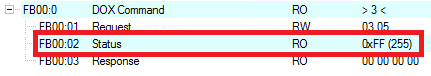 Fig.189: Command status in case of successful storage of the output voltage