Hardware enable
 | Available from FW04 The function described in this chapter for the use of the flash signal of a camera can only be used from FW04 onwards. |
The trigger input also has an enable function for the hardware. If there is a preset signal (TRUE or FALSE) at the trigger input, the hardware of the EL2596 is activated and outputs can be actuated. One possible application is the “flash signals” of some cameras.
By default, some camera types have an output signal that is set to TRUE for the exposure time required. This signal from the camera is also referred to as a “flash signal”. If the flash signal of a camera is to be used as a trigger/enable input and the LED output is switched accordingly for as long as the trigger input of the flash signal of the camera is TRUE (LED output = flash signal), the hardware enable must be activated.
The “Hardware enable” function can be used in all operation modes. When using the “Hardware enable” in the operation mode “Current control trigger input” it should be noted, however, that the LED is then operated continuously as long as the signal is applied to the trigger input and not only for the specified pulse duration with the specified pulse delay. Consequently, the output is synchronous with the trigger input.
In addition to the LED output, the trigger output can also only be used in the trigger input mode “Hardware enable” if the hardware is activated by a signal at the trigger input.
To enable and use this function, the following settings of the EL2596xxxx are necessary:
- Connect the flash signal to pins 5 (TrigIn+) and 13 (TrigIn-).
- Select the desired operation mode in the CoE index 0x8004:01.
- Select “Hardware Enable” as the input function for the trigger input in the CoE index 0x8002:32
- In the CoE index 0x8002:30 “Invert digital input” set whether the hardware is to be enabled on a TRUE or FALSE signal
- “Invert digital input” TRUE = enabled on FALSE at trigger input
- “Invert digital input” FALSE = enabled on TRUE at trigger input
- Set all mode-specific parameters in the PDOs as described in Setting the operation modes.
- Activate the control under “DOX Control” → “Control” via the “Enable” bit.
- Switch on the LED output under “DOX Control” → “Control” by activating the “Output” bit.
- The LED output or trigger output is now TRUE as long as the signal is active at the trigger input.
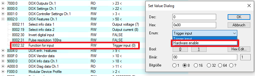 Fig.202: Set the input mode “Hardware enable”