Current control PWM
This mode allows the control of an LED by pulse width modulation. The amplitude of the output current is controlled by an analog circuit. This leads to additional self-heating. In order to prevent damage to the module, the output power is automatically limited in this mode by reducing the maximum accepted value for the duty cycle. The maximum accepted value can be calculated by
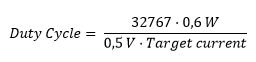
Higher entries will be ignored.
Due to the high self-heating in PWM operation, the theoretically maximum calculated value for the duty cycle cannot always be reached. The following figure shows the correlation between the maximum possible duty cycle in combination with the output voltage for 5 different output current values at an ambient temperature of 55 °C. At higher duty cycle settings, the EL2596 would have switched off temporarily due to overtemperature. The following figure gives guide values and does not necessarily apply to every application.
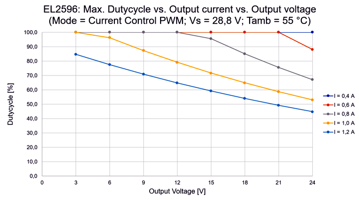 Fig.166: EL2596 | maximum duty cycle in current control PWM mode
For the EL2596-0010 for operation without fan in Current control PWM mode the following limitation for the maximum duty cycle must be considered:
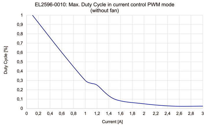 Fig.167: EL2596-0010 | maximum duty cycle in current control PWM mode
For true-color dimming, the set limit current in the target current and the desired output current should correspond to the nominal current of the LED.
In this operation mode, it is possible to configure the trigger input as an enable input so that it can be used as an external switch. An output can then only be actuated with a specified signal at the trigger input. More detailed information and commissioning can be found in the chapter Hardware enable.
The specific parameters for controlling the LED output via PWM are described below.
- Nominal/limit current of the LED in the unit mA in index 0x8000:02 “Target current”
- Input voltage in the unit 0.01 V in the index 0x8000:03 “Supply voltage”
- Desired output voltage in the unit 0.01 V (max. UIN - 2 V) in the index 0x8000:04 “Output voltage”. In this operation mode, the value set here corresponds to the output on the controller. If the forward voltage of the connected LED is lower than the value set here, the remaining voltage drops internally in the EL2596. In many cases, this leads to overtemperature in the terminal and thus to the switching off of the LED output. As the desired output voltage, therefore, the forward voltage at the desired output current should be set here. The TeachIn function can also be used to determine the output voltage.
- The default PWM frequency is 1050 Hz. If necessary, the value can be adjusted in index 0x8004:04.
WARNING
- Set the operation mode in the CoE directory in the index 0x8004:01 to “Current Control PWM”
- Set the predefined PDO assignments to “PWM (with info data)” or “PWM with current (and info data)”
- Only for Predefined PDO "PWM with current (and info data)": Specify the set current in the unit mA via “DOX Current” → “Output Current”
- Specify “PWM duty cycle” under “DOX PWM duty” → “PWM duty”. If the PDO object 0x1604 “DOX PWM duty” is not mapped, the duty cycle is specified in the CoE index 0x8004:07.
- Check under “DOX Status” → “Status” whether the “Ready to activate” bit is 1
- Activate the control under “DOX Control” → “Control” via the “Enable” bit
- Switch on the LED output under “DOX Control” → “Control” by activating the “Output” bit
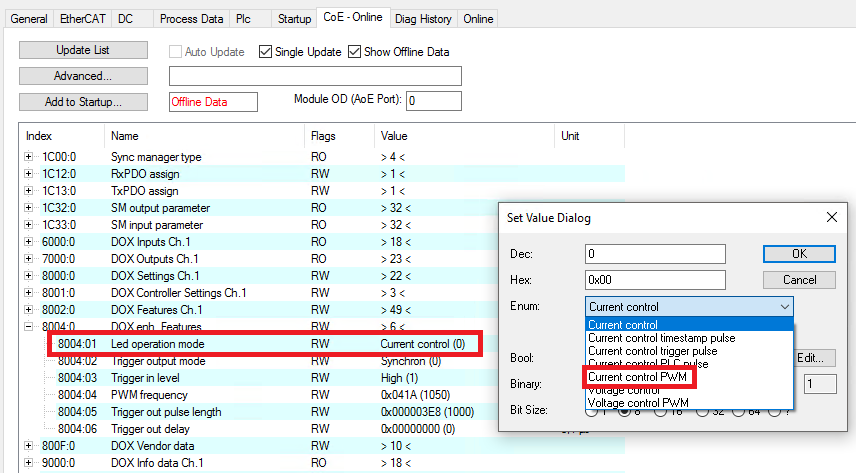 Fig.168: Operation mode setting “Current control PWM”
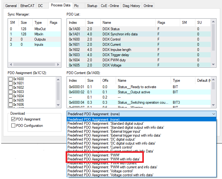 Fig.169: PDO setting “PWM (with info data)”
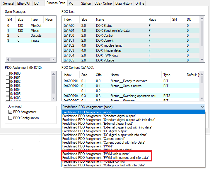 Fig.170: PDO setting “PWM with current (and info data)”
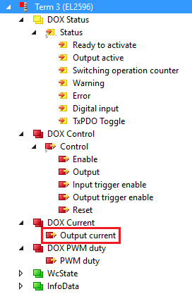 Fig.171: Setting the set current
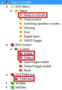 Fig.172: Activating the output in the operation mode “Current control PWM”