Further characteristics
Characteristic | Explanation |
|---|---|
On/off trigger | The load can be switched on/off on a common time base with Distributed Clocks by timestamp or "frame-triggered" by the EtherCAT frame. |
Switching characteristics | The output circuit of the EL2212 is optimized for fast signal output, even at higher currents. For this purpose, the EL2212 has a full bridge for each channel, which switches actively to 24..72 V (positive operating voltage), 0 V or reverse polarity to -24..-72 V. The terminal is protected against overcurrent and short-circuit. The power supply of the EL2212 should be dimensioned according to the power requirements of the connected actuators. The power supply lines, power supply unit and actuator lines should be suitably short or generous respectively. |
Tristate | In Tristate mode each channel can be switched to high-resistance. This state ensures that the respective output behaves as if it was not connected, so that it does not influence the outputs of other outputs/devices connected in parallel. The associated output takes on the same output voltage as the other active devices. |
Internal PWM | As the "internal PWM", the frequency of the current control or basic PWM frequency cannot be changed and is implemented separately to the external PWM, which is controllable by the user. The frequency is typically 32 KHz. |
External PWM | It is possible to output the switched outputs with pulse-width modulation. The activation, period duration and duty factor of this "external PWM" can be controlled by means of CoE object or PDO (see "Activation of the external PWM"). The terminal automatically switches the output on and off independently of the preset on/off time stamp. Three levels therefore have to be considered in terms of time: |
Short circuit protection | The short-circuit current of each channel is typically limited to 12 A. The EL2212 reports Error via the process data and deactivates both channels. A Reset via the control word resets the terminal. |
OpenLoad detection | The OpenLoad detection is active only between the boost-on and boost-off phases if the output is set and boost on/off is activated. If a current of less than 100 mA is measured at the respective output after the boost-on of the terminal, this is detected as an "OpenLoad". If the output is permanently switched on, there may be a delay of approx. 500 ms in detecting the open load. The corresponding bit (DOX Diag Data) 0xApp0:07 is set when such missing loads are detected. This detection is not active if PWM is activated. |
Characteristic | Explanation |
Overtemperature protection | The EL2212 is protected against overtemperature. Internal temperature measurement takes place.
The current internal temperature of the terminal and the limit temperature can be read out via the diagnostic elements in the CoE object 0xF900. |
Multi-time stamping | Up to 10 independent switching orders can be transferred to one channel or two channels in one PLC task cycle of the terminal; these orders are executed in accordance with the time stamps transferred. Due to the 32 bit width of the time stamp, the future order times can be approx. 4.29 s at the most starting from the current DC time inside the PLC controller. |
Phase times | Both the boost-on and the boost-off phase can be set to a maximum of 100 ms. |
Inductive load | The voltage peaks when switching the inductive load are effectively controlled by the output stage of the EL2212. |
Watchdog | The SM-Watchdog can be deactivated or changed. It is set to 100 ms as standard. |
Coil resistance | Due to the internal calculations, the max. permissible coil resistance according to CoE object 0x80n0:05 is limited to 244 Ω. |
Characteristic | Explanation |
Actuator, recommended power range | The accuracy of the current measurement is typically ±100 mA. It is therefore recommended to work with boost and holding currents of > 200 mA. This results in the following maximum permissible internal actuator resistance, depending on the supply voltage of the EL2212:
|
Switch-on/switch-off delay, power driver | The delay time before the switching order is output via the PWM stage is typically 20 µs for the switch-on and switch-off procedure without Distributed Clocks. In view of the inertia of the load (ms range) this is usually relatively negligible. In order to achieve the most exact activation in terms of time, this constant offset can be taken into account in Distributed Clocks mode.
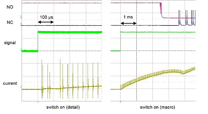
Switch-on procedure of a relay, in detail and complete switching procedure |
Minimum cycle time | The minimum permissible cycle time with and without Distributed Clocks mode is 100 µs. |
Firmware Update | The firmware update can be carried out only with the supply voltage applied. |
BoostOn current curve | The current curve in the Boost-On is of great interest during commissioning. Ideally, current/voltage is monitored externally with an oscilloscope. If this is not available, the following feature of the EL2212 can be used to estimate the current in the Boost-On phase: The EL2212 also monitors the current per channel in the noncurrent-controlled boost-on phase. The user can enter 3 current limits (Boost Current Treshold, BCT) in the CoE 0x80n0:0C..9E:
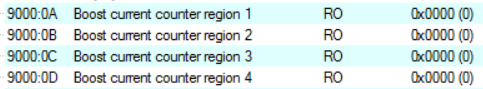
If the current in the Boost-On phase exceeds the respective limit, the firmware counts up the BCC (Boost current counter region) accordingly in CoE 0x90n0:0A..0D:
The following applies: BCC 1 for Current < BCT 1 BCC 2 for Current < BCT 2 BCC 3 for Current < BCT 3 BCC 4 for Current > BCT 3 The counters are reset by an EtherCAT restart of the INIT->OP terminal. |
Boost times | The boost-on time (0x80n0:06) and the boost-off time (0x80n0:07) can be a maximum of 100 ms. |