Activation of the external PWM
Apart from the internal PWM used for current control, the EL2212 terminal can additionally drive an output load with pulse width modulation. This way the current of the load can be subsequently influenced. Since the terminal already uses a PWM for the internal current control, this user-controllable PWM is called "external PWM".
Starting with the energization of a relay (24 V / 200 mA), initially without activated external PWM, the energization of a relay with PWM is shown afterwards.
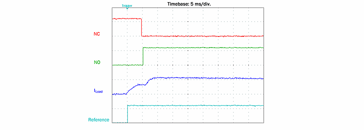 Fig.145: Oscilloscope recording: Energization of a relay without PWM
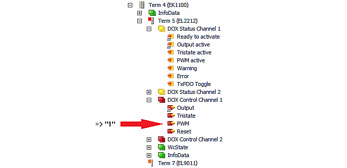
In order to activate the external PWM control of the EL2212, the period duration (Tperiod) of the PWM must be entered in object 0x8000:0A and the switch-off time (Toff) in object 0x8000:0A in "DOX Settings". Furthermore, True must be entered in the associated "DOX Features" object 0x8002:04 (Enable PWM Output). The PWM is switched through with the PDO (0x1600) "DOX Control Channel 1" → "PWM" (set to "1"):
For example, values of 2/4 ms are initially entered for Toff/Tperiod respectively for a duty factor of 50%, which is equivalent in principle to half a holding current:
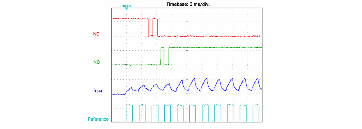 Fig.146: Energization of a relay with PWM 50%
The NC/NO contacts show subsequent switching with bouncing contacts. However, this can be held after the activation of the armature.
In the case of an even smaller duty factor, e.g. 25% (Toff/Tperiod = 1/4 ms), the relay armature is no longer moved; on the other hand, with a correspondingly larger duty factor, e.g. 75%, it is delayed but without bouncing:
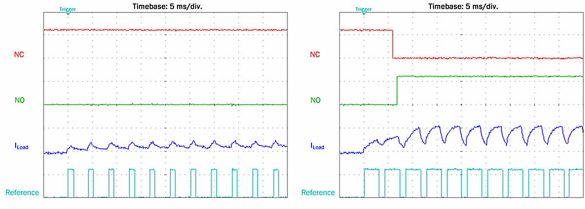 Fig.147: Energization of a relay: left with PWM 25%, right with PWM 75%
The PWM can also be switched in with boost-on/boost-off activated. Note that there is no longer any open load detection.
 | Limited error detection with PWM activated If PWM is activated, an interruption in the current supply from the terminal to the load is no longer automatically detected; i.e. in case of an open circuit with the output activated, neither the setting of the corresponding bits in the DOX Diag Data takes place nor is an error generally displayed (no error bit / error LED) |
Controlling PWM by means of PDO (direct access by PLC program)
Furthermore, by switching in the PDO assignments for 0x1C12 (on the "Process data" tab) of 0x1605 (for channel 1) and 0x1606 (for channel 2), setting parameters for the period duration and duty factor can be added to the process data, as the following illustration shows:
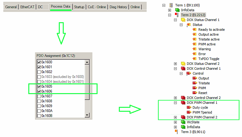 Fig.148: Adding the process data objects "Duty Cycle" and "Tperiod"
After re-activating the configuration via the TwinCAT user interface, it is then possible to overwrite the values for "Tperiod" and "Toff" contained in the CoE by PDO access. A CoE write command is not required for the PDO access – the new PDOs can be directly linked to PLC variables.
The following must be observed:
- Duty Cycle (PDO)
- The energization can be completely switched off with a duty cycle value of "0".
- A value of 100 to 255 leads to a PWM-free energization.
- Tperiod (PDO/CoE)
- If the value "0" has been written into the PDO "PWM Tperiod", the Tperiod value set in 0x8000:09 in the CoE will be used again for the generation of the PWM.
- As opposed to the CoE entry, values smaller than 20 and thus a PWM frequency of up to 10 KHz can be set via the PDO "PWM Tperiod". The CoE entry is limited to 20 *0.1 ms and the PWM frequency therefore to 500 Hz.
- Toff (CoE)
- The CoE entry "Toff" (0x8000:0A) has no effect as long as the PDOs (channel-specific: 0x1605 or 0x1606) are configured via the process data.