Process data
The process data overview lists the detailed PDO selection. These data are not usually necessary for operation under TwinCAT, since they can be simply configured from the configuration interface via the process data preselection.
Preselection of process data
An EtherCAT device usually offers several different process data objects (PDO) for input and output data, which can be configured in the System Manager, i.e. they can be activated or deactivated for cyclic transmission. See further below for the corresponding overview. Attention is thereby to be paid to the compatibility of input and output PDO.
From TwinCAT 2.11 with the EtherCAT devices intended for the purpose according to the ESI/XML description, the process data for input and output can be activated simultaneously by appropriate predefined sentences, "predefined PDO".
In the "Process Data" tab, the EL2212 has
 Fig.149: "Process Data" tab
the following 'predefined PDO' sentences:
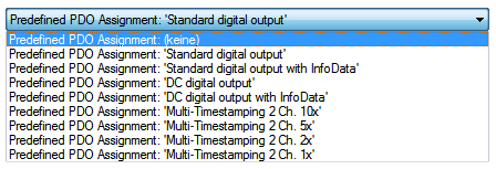 Fig.150: TwinCAT System Manager with the PDO selection
In detail the sentences are composed as follows:
Operation mode | Name | SM2, PDO assignment | SM3, PDO assignment |
|---|---|---|---|
SM-synchronous “frame-triggered” | Standard digital output (default setting) | 0x1600 | 0x1A00 |
Standard digital output with InfoData | 0x1600 | 0x1A00 | |
DistributedClocks-triggered | DC Digital output | 0x1600 | 0x1A00 |
DC Digital output with InfoData | 0x1600 | 0x1A00 | |
Multi-Timestamping 2 Ch. 10x | 0x1603 | 0x1A05 | |
Multi-Timestamping 2 Ch. 5x | 0x1603 | 0x1A05 | |
Multi-Timestamping 2 Ch. 2x | 0x1603 | 0x1A05 | |
Multi-Timestamping 2 Ch. 1x | 0x1603 | 0x1A05 |
Explanation of the process data
Standard digital output (default)
The outputs can be written directly with this standard PDO assignment, i.e. the connected actuators can be switched frame-triggered directly.
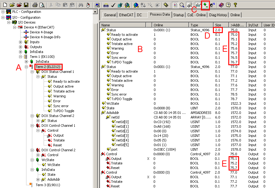 Fig.151: Standard EL2212 process image
 The EL2212 (A) has 2-byte variables at its disposal with different bit meanings. These can be seen by expanding the tree (A). They are also displayed in the detail view (B) if the appropriate display function (C) is activated.
The bit meaning i.e. offset position can then also be taken from the memory assignment display (E), taking into account the variable size (D).
Both the collective name e.g. Status and the individual bit variable e.g. OutputActive can be linked, but not both at the same time.
Input data | |||
|---|---|---|---|
Collective name | Name | Description / function | Bit position [0 - 15] |
Status | Ready to activate | The terminal signals its readiness for operation here. | 0 |
| Output active | The output is actively switched. | 1 |
| Tristate active | The output drivers are connected with high resistance; the load is connected neither to GND nor to the supply voltage | 2 |
| PWM active | The PWM is actively switched to the output n. | 3 |
| Warning | A warning has occurred - > evaluate “Diag data” (index 0xA000). | 6 |
| Error | An error has occurred and the output drivers are deactivated - > evaluate “Diag data” (index 0xA000). | 7 |
| TxPDO Toggle | Changes its state each time process data are exchanged. | 15 |
WcState |
| Setpoint during operation: 0 Each datagram of the EL2212 indicates its processing state here. This allows the EL2212 to be monitored for correct process data communication. |
|
InfoData (State) |
| Setpoint during operation: 8 Status display of the “EtherCAT state machine” |
|
AdsAddr |
| AMS address of the responsible EtherCAT Master in the format "0.0.0.0.0.0". In addition, the port number valid for this Slave. Required for acyclic accesses to the CoE at runtime. |
|
Note: The EL2212 supplies 2 different status words (16 bit):
- As specified here in the cyclic PDO
- In CoE 0x90n0:01 there is a further 16 bit status word with more information. This can be read out via ADS or mapped into the cyclic PDO InfoData
Output data | |||
|---|---|---|---|
Collective name | Name | Description / function | Bit position [0 - 15] |
Control
| Output | Activate the output of channel n | 1 |
Tristate | Switch channel n to high resistance | 2 | |
PWM | Switching PWM through | 3 | |
Reset | Reset of an error on channel n | 7 | |
 | Observe priorities If the two signals “Output” and “Tristate” are activated at the same time, “Tristate” has a higher priority. |
Standard digital output with InfoData
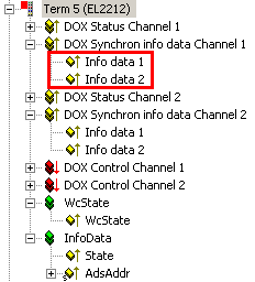 Fig.152: Additional information data
Two further cyclic data words can be displayed per channel for more exact information about the states of the actuators or the driver stage. The respective selection is to be configured via the appropriate Index 0x80n2:11 in the CoE. Among other things, the interior temperature of the terminal or the momentary current through the connected actuator can be selected, for example.
Input data | |
|---|---|
Name | Description / function |
Info data 1 | Additional channel information, definition in 0x80n2:11 |
Info data 2 | Additional channel information, definition in 0x80n2:19 |
DC Digital output
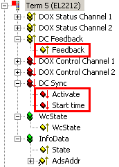 Fig.153: Additional process data for Distributed Clocks mode
In Distributed Clocks mode the EL2212 works according to timestamp order like the EL2252. Accordingly the process image is the same.
Input data | |
|---|---|
Name | Description / function |
Feedback | The terminal returns the current state of the output channels in this byte. This can be used to check a switching order. |
Output data | |
|---|---|
Name | Description / function |
Activate | This byte activates a new start time in the terminal through the transition 0 --> 3 The sequence:
Only one switching order with the target states of both channels (output, tristate) can be conveyed to the EL2212/EL2252. After the expiry of the order the terminal is ready for a new switching order, unless the existing order is overwritten beforehand. |
Start time | 64-bit value of the next desired switching event. The data of the DC time:
|
| Switching time The desired switching time must be far "enough" in the future, as seen from the time of calculation, in the NC/PLC in order to be capable of being conveyed to the terminal, including activation. Since 2 EtherCAT cycles are required for the activation, it is recommended not to make this interval smaller than 3 cycles. |
DC Digital output with InfoData
Like both standard data types, additional information data can also be displayed in DC mode. See above.
Multi-time stamping
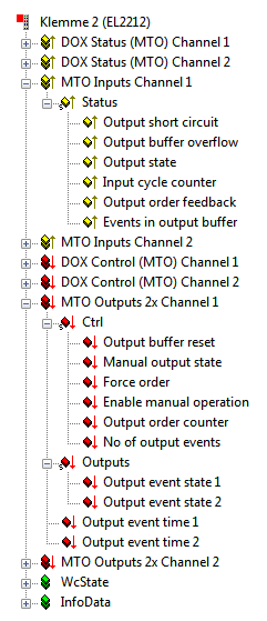 Fig.154: Process data in multi-time stamping mode (2-fold oversampling)
The multi-time stamping supports two channels, each with 1-fold, 2-fold, 5-fold or 10-fold oversampling. The factor indicates the maximum number of events that can be loaded into the output buffer for each EtherCAT cycle.
Input data | |
|---|---|
Name | Description / function |
Output short circuit | Output has a short-circuit/overload. |
Output buffer overflow | More events have been written into the buffer than the number of free elements available. |
Output state | Current state of the output. |
Input cycle counter | Update counter of the PLC input data. |
Output order feedback | Feedback of the order counter. |
Events in output buffer | Current number of events remaining in the buffer. |
Output data | ||
|---|---|---|
Name | Description / function | |
Ctrl | Output buffer reset | Clear all events in the output buffer. |
Manual output state | Set the output permanently to this value (can be activated via CoE and PDO, see Enable manual operation). | |
Force order | If "1", already expired events are also output. Relevant only if time stamp checking is activated, "Enable time check" = "1". See detailed explanation below. | |
Enable manual operation | Allow manual operation via the PDO bit "Manual output state". | |
Output order counter | Incrementation of this value indicates to the terminal that there are new values in the PDO. | |
No of output events | Number of events deposited in the PDO | |
Outputs | Output event state n | Output value at the time of the nth time stamp |
Output event time n | Time stamp of the nth event | |
The EL2212 is processing multi timestamp requests by a clock of 25 µs and decides within this interval whether an execution is pending or not. Accordingly the feasible time resolution and therefore the time accuracy of the electrical switching signal is 25 µs also.
Detailed explanation of Enable time check/ Force order
The use of the time stamp check "Enable time check" = "1" is illustrated in the following in three modes in connection with the PDO "Force order":
|
Mode |
Enable time check |
Force Order |
Effect | |
|---|---|---|---|---|
|
1 |
0 |
- |
Time stamp check inactive, i.e. starting from the current DC time value, time stamps lying more than 100 µs in the past will be interpreted as future time stamps, which can lead to a delay of up to 4.29 s in transmissions of the states. | |
|
2 |
1 |
0 |
No output of obsolete events |
Time stamp check active; the time interval of the time stamp to be transmitted is distributed over ±231, i.e. approx. 2.15 s in the past and approx 2.15 s in the future. The latter represents a lowered limit of the time range from approx. 4.29 s to approx. 2.15 s. |
|
3 |
1 |
1 |
Immediate output of the obsolete event | |
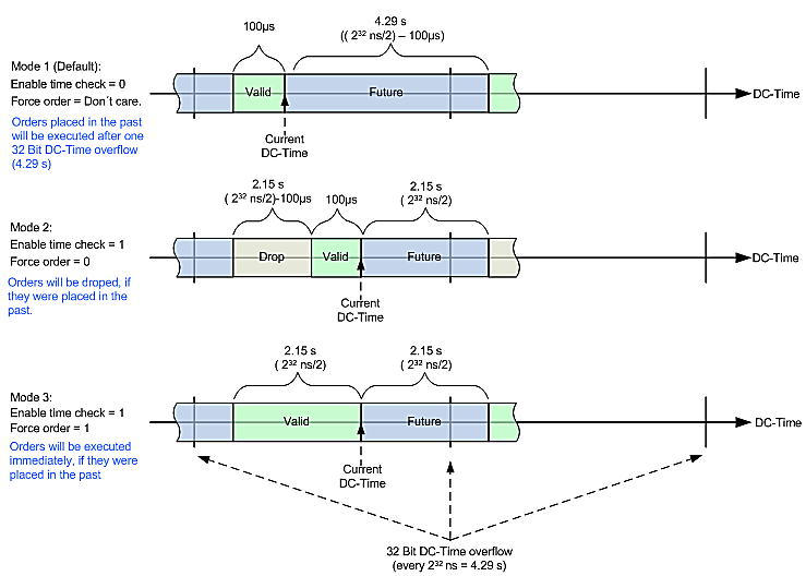 Fig.155: Treatment of the time stamp of the output states with activated time stamp check
Notice | |
Conditions for time stamps in the case of multi-time stamping
|
Process data overview
Manual process data assignment is necessary for TwinCAT up to version 2.10.
Sync Manager (SM)
The extent of the process data that is made available can be changed through the "Process data" tab (see following figures).
The PDOs from the range 0x160n (0x1600, 01x1601, 0x1602) can be assigned to the Output SyncManager, see fig. "Process Data Sync Manager with Outputs tab",
the PDOs from the range 0x1A0n (0x1A00 to 0x1A049) to the Input Sync manager, see fig. "Process Data Sync Manager with Inputs tab".
Not all combinations are technically possible
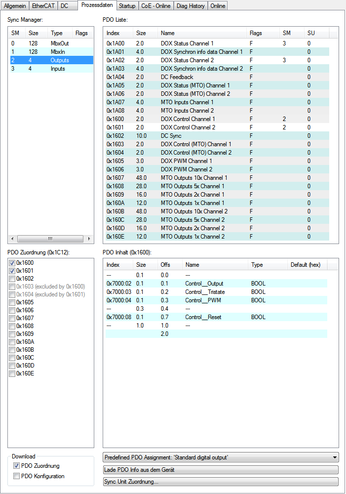 Fig.156: Process Data SM2 (Outputs) tab, EL2212 (default)
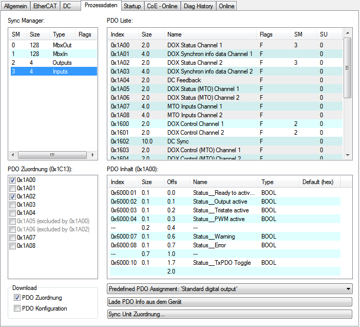 Fig.157: Process Data SM3 (Inputs) tab, EL2212 (default)
Manual PDO Assignment
In order to configure the process data, mark the desired Sync Manager "Inputs" or "Outputs" (both are editable) in the upper left-hand "Sync Manager" box. The process data assigned to this Sync Manager can then be switched on or off in the “PDO Assignment” box underneath. Restarting the EtherCAT system, or reloading the configuration in configuration mode (F4), causes the EtherCAT communication to restart, and the process data is transferred from the terminal.
|
SM2 (Outputs), PDO assignment 0x1C12 | ||||
|---|---|---|---|---|
|
Index |
Index of excluded PDOs |
Size (byte.bit) |
Name |
PDO content |
|
0x1600 (default) |
0x1603 |
2.0 |
DOX Control |
Index 0x7000:02 - Output Index 0x7000:03 - Tristate Index 0x7000:04 - PWM Index 0x7000:08 - Reset |
|
0x1601(default) |
0x1604 |
2.0 |
DOX Control |
Index 0x7010:02 - Output Index 0x7010:03 - Tristate Index 0x7010:04 - PWM Index 0x7010:08 - Reset |
|
0x1602 |
0x1607 |
10.0 |
DC Sync possible exclusively in conjunction with the DC operating mode! |
Index 0xF700:01 - Activate Index 0xF700:03 - Start time |
|
0x1603 |
0x1600 |
2.0 |
DOX Control (MTO) |
Index 0x7000:04 - PWM Index 0x7000:08 - Reset |
|
0x1604 |
0x1601 |
2.0 |
DOX Control (MTO) |
Index 0x7010:04 - PWM Index 0x7010:08 - Reset |
|
0x1605 |
- |
3.0 |
DOX PWM |
Index 0x7000:11 - Duty cycle Index 0x7000:13 - PWM Tperiod |
|
0x1606 |
- |
3.0 |
DOX PWM |
Index 0x7010:11 - Duty cycle Index 0x7010:13 - PWM Tperiod |
|
0x1607 |
0x1602 |
48.0 |
MTO Outputs 10x |
Index 0x7021:01 - Output buffer reset Index 0x7021:02 - Manual output state Index 0x7021:03 - Force order Index 0x7021:04 - Enable manual operation Index 0x7021:09 - Output order counter Index 0x7021:11 - No of output events Index 0x7021:21 - Output event state 1 Index 0x7021:22 - Output event state 2 Index 0x7021:23 - Output event state 3 Index 0x7021:24 - Output event state 4 Index 0x7021:25 - Output event state 5 Index 0x7021:26 - Output event state 6 Index 0x7021:27 - Output event state 7 Index 0x7021:28 - Output event state 8 Index 0x7021:29 - Output event state 9 Index 0x7021:2A - Output event state 10 Index 0x7021:41 - Output event time 1 Index 0x7021:42 - Output event time 2 Index 0x7021:43 - Output event time 3 Index 0x7021:44 - Output event time 4 Index 0x7021:45 - Output event time 5 Index 0x7021:46 - Output event time 6 Index 0x7021:47 - Output event time 7 Index 0x7021:48 - Output event time 8 Index 0x7021:49 - Output event time 9 Index 0x7021:4A - Output event time 10 |
|
0x1608 |
0x1602 |
28.0 |
MTO Outputs 5x |
see 0x1607 with accordingly fewer events |
|
0x1609 |
0x1602 |
16.0 |
MTO Outputs 2x |
see 0x1607 with accordingly fewer events |
|
0x160A |
0x1602 |
12.0 |
MTO Outputs 10x |
see 0x1607 with accordingly fewer events |
|
0x160B |
0x1602 |
48.0 |
MTO Outputs 10x |
Index 0x7031:01 - Output buffer reset Index 0x7031:02 - Manual output state Index 0x7031:03 - Force order Index 0x7031:04 - Enable manual operation Index 0x7031:09 - Output order counter Index 0x7031:11 - No of output events Index 0x7031:21 - Output event state 1 Index 0x7031:22 - Output event state 2 Index 0x7031:23 - Output event state 3 Index 0x7031:24 - Output event state 4 Index 0x7031:25 - Output event state 5 Index 0x7031:26 - Output event state 6 Index 0x7031:27 - Output event state 7 Index 0x7031:28 - Output event state 8 Index 0x7031:29 - Output event state 9 Index 0x7031:2A - Output event state 10 Index 0x7031:41 - Output event time 1 Index 0x7031:42 - Output event time 2 Index 0x7031:43 - Output event time 3 Index 0x7031:44 - Output event time 4 Index 0x7031:45 - Output event time 5 Index 0x7031:46 - Output event time 6 Index 0x7031:47 - Output event time 7 Index 0x7031:48 - Output event time 8 Index 0x7031:49 - Output event time 9 Index 0x7031:4A - Output event time 10 |
|
0x160C |
0x1602 |
28.0 |
MTO Outputs 5x |
see 0x160B with accordingly fewer events |
|
0x160D |
0x1602 |
16.0 |
MTO Outputs 2x |
see 0x160B with accordingly fewer events |
|
0x160E |
0x1602 |
12.0 |
MTO Outputs 10x |
see 0x160B with accordingly fewer events |
|
SM3 (Inputs), PDO Assignment 0x1C13 | ||||
|---|---|---|---|---|
|
Index |
Index of excluded PDOs |
Size (byte.bit) |
Name |
PDO content |
|
0x1A00 (default) |
0x1A05 |
2.0 |
DOX Status |
Index 0x6000:01 - Ready to activate Index 0x6000:02 - Output active Index 0x6000:03 - Tristate active Index 0x6000:04 - PWM active Index 0x6000:07 - Warning Index 0x6000:08 - Error Index 0x6000:10 - TxPDO Toggle |
|
0x1A01 |
- |
4.0 |
DOX Synchron info data | |
|
0x1A02 (default) |
0x1A06 |
2.0 |
DOX Status |
Index 0x6010:01 - Ready to activate Index 0x6010:02 - Output active Index 0x6010:03 - Tristate active Index 0x6010:04 - PWM active Index 0x6010:07 - Warning Index 0x6010:08 - Error Index 0x6010:10 - TxPDO Toggle |
|
0x1A03 |
- |
4.0 |
DOX Synchron info data |
Index 0x6010:11 - Info data 1 Index 0x6010:12 - Info data 2 |
|
0x1A04 |
0x1A07 |
2.0 |
DC Feedback possible exclusively in conjunction with the DC operating mode! |
Index 0xF600:01 - Feedback |
|
0x1A05 |
0x1A00 |
2.0 |
DOX Status (MTO) |
Index 0x6000:01 - Ready to activate Index 0x6000:04 - PWM active Index 0x6000:07 - Warning Index 0x6000:08 - Error Index 0x6000:10 - TxPDO Toggle |
|
0x1A06 |
0x1A02 |
2.0 |
DOX Status (MTO) |
Index 0x6010:01 - Ready to activate |
|
0x1A07 |
0x1A04 |
4.0 |
MTO Inputs |
Index 0x6020:01 - Output short circuit Index 0x6020:02 - Output buffer overflow Index 0x6020:03 - Output state Index 0x6020:0F - Input cycle counter Index 0x6020:11 - Output order feedback Index 0x6020:12 - Events in output buffer |
|
0x1A08 |
0x1A04 |
4.0 |
MTO Inputs |
Index 0x6030:01 - Output short circuit Index 0x6030:02 - Output buffer overflow Index 0x6030:03 - Output state Index 0x6030:0F - Input cycle counter Index 0x6030:11 - Output order feedback Index 0x6030:12 - Events in output buffer |