Connections
The basic CPU module is available with different hardware and software options. It is supplied from the power supply unit, so that only the connections are described here.
Basic CPU module with 2 Ethernet RJ 45 interfaces:
RJ 45 interface (socket):

PIN | Signal | Description |
|---|---|---|
1 | TD + | Transmit + |
2 | TD - | Transmit - |
3 | RD + | Receive + |
4 | connected | not used |
5 | ||
6 | RD - | Receive - |
7 | connected | not used |
8 |
TD & RD are exchanged at the hubs or between two PCs.
Schematic structure of the network components:
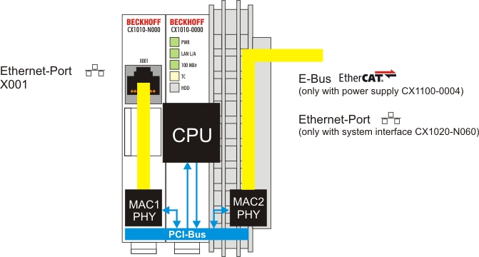
The CX1010 features two MAC blocks. The first one (MAC1) operates the left network interfaces for the standard IP network. This port is also used for PLC programming.
The second block (MAC2) operates the extended PC104 bus. The second physical network connection can be utilized via additional system interfaces. This requires either a CX1100-0004 power supply unit or a CX1020-N060 system interface. A connection to the E-bus for EtherCAT terminals is realized via the power supply unit. The CX1010-N060 interface establishes the Ethernet connection, thereby making a further network interface available.
Operating system perspective:
The operating system only sees the connections for the network interface. The internal connection via the PC104 bus extension is shown as the second interface. If no expansion module is connected, the line is reported as not connected. If the CX1100-0004 power supply unit is connected, Windows XPe reports "restricted or no connection". This behavior is normal, since Windows itself does not use this interface, and therefore no IP address is allocated. If the CX1020-N060 extension is connected, the connection behaves like a 'normal' network port.
 | The network ports are only for communication with standard network. Do not connect to telecommunication circuits. |
Basic CPU module with DVI/USB interface:
In addition to the Ethernet port, this basic module also features DVI/USB interfaces. The pin assignment of the basic CPU module with two USB and a DVI-I interface is explained under the associated CX1010-N 010 system interface.
Applicable to all basic CPU modules:
LED
The green power LED (PWR) is on if the basic CPU module is connected correctly to a live power supply unit.
Compact Flash slot
Further information can be found under Compact Flash slot.
PC 104 Bus
The PC 104 bus is a standardized bus with 104 ISA signals for compact embedded systems.