PC/104 Bus
The PC 104 bus is a standardized bus with 104 ISA signals for compact embedded systems.
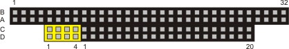
For the functionality of the CX1020 modules eight further signals have been added ( here marked with color).
Pin |
|
| Row C4 | Row D4 |
|---|---|---|---|---|
1 | IOCHCHK* | GND | GND | GND |
2 | SD7 | RESETDRV | SBHE* | MEMCS16* |
3 | SD6 | +5V | LA23 | IOCS16* |
4 | SD5 | IRQ9 | LA22 | IRQ10 |
5 | SD4 | n.c. (+12V internal) | LA21 | IRQ11 |
6 | SD3 | DRQ2 | LA20 | IRQ12 |
7 | SD2 | n.c. (+5V internal) | LA19 | IRQ13 |
8 | SD1 | ENDXFR* | LA18 | IRQ14 |
9 | SD0 | +12V | LA17 | DACK0* |
10 | IOCHRDY | (KEY)² | MEMR* | DRQ0 |
11 | AEN | SMEMW* | MEMW* | DACK5* |
12 | SA19 | SMEMR* | SD8 | DRQ5 |
13 | SA18 | IOW* | SD9 | DACK6* |
14 | SA17 | IOR* | SD10 | DRQ6 |
15 | SA16 | DACK3* | SD11 | DACK7* |
16 | SA15 | DRQ3 | SD12 | DRQ7 |
17 | SA14 | DACK1* | SD13 | +5V |
18 | SA13 | DRQ1 | SD14 | MASTER* |
19 | SA12 | REFRESH* | SD15 | GND |
20 | SA11 | SYSCLK | (KEY)² | GND |
21 | SA10 | IRQ7 | -- | -- |
22 | SA9 | IRQ6 | -- | -- |
23 | SA8 | IRQ5 | -- | -- |
24 | SA7 | IRQ4 | -- | -- |
25 | SA6 | IRQ3 | -- | -- |
26 | SA5 | DACK2* | -- | -- |
27 | SA4 | TC | -- | -- |
28 | SA3 | BALE | -- | -- |
29 | SA2 | +5V | -- | -- |
30 | SA1 | OSC | -- | -- |
31 | SA0 | GND | -- | -- |
32 | GND | GND | -- | -- |
Remarks:
1. B10 and C19 are key locations.
2. Signal timing and function are as specified in ISA specification.
3. Signal source/sink current differ from ISA values.
4. Negative voltages are not supported.
5. in the specification the pins are counted from 0 to 19
Assignment on the 8 additional pins
Pin number (yellow fields) |
|
|
|---|---|---|
1 | LAN TX- | LAN TX+ |
2 | LAN RX- | LAN RX+ |
3 | USB D- | USB D+ |
4 | SMBDAT | SMBCLK |
Note:
Further information to PC104 Bus can be found in the datasheet or under http://www.pc104.org.