MC_PathDigitalCamSwitch_MultiEdge
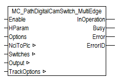
MC_PathDigitalCamSwitch_MultiEdge is a digital cam controller with one or several cams on a digital output track. The function block is capable of performing several switching operations during a PLC cycle. The switching operations are defined by position cams. Further output tracks can be realized with independent instances of the function block.
In addition to the switching states of the digital output the output data structure contains precise time information for the next switching operations. With this information the actual output can take place on an XFC multi-timestamp output terminal with a downstream function block (XFC_EL1259_MultiEdge, XFC_EL2212_MultiEdge, XFC_EL2262_MultiEdge or XFC_EL2258_MultiEdge).
Note
Inputs
VAR_INPUT
    Enable  : BOOL;
    HParam  : DINT;
    Options : ST_CamSwitchOptions;
END_VAR
|
Enable |
The cam controller is activated via the Enable input. The initial state remains unchanged, as long as Enable=FALSE. | |
|
HParam |
H-parameter value that corresponds to the switching state TRUE. | |
|
Options |
Optional parameters | |
|
Options. |
EncoderIndex |
If more than one encoder is connected to the axis, the encoder index [0 – 9] can be defined here. The first encoder has the index 0. |
|
Options. |
UseAcceleration |
UseAcceleration can be set to TRUE in order to incorporate the acceleration of the axis into the position calculation. UseAcceleration can be advantageous if the setpoint values of the acceleration can be used. UseAcceleration may be disadvantageous with encoder axes that supply a noisy position signal, because the acceleration is also erroneous. |
Outputs
VAR_OUTPUT
    InOperation : BOOL;
    Busy        : BOOL;
    Error       : BOOL;
    ErrorID     : UDINT;
END_VAR
|
InOperation |
InOperation is TRUE, as long as the cam controller is active and the cam track is calculated according to the cam parameterization. |
|
Busy |
Busy is TRUE as long as the block function is not completed. |
|
Error |
Becomes TRUE if an error occurs. |
|
ErrorID |
If the error output is set, this parameter supplies the error number |
Inputs/outputs
VAR_IN_OUT
    NciToPlc     : NciChannelToPlc
    Switches     : PATH_CAMSWITCH_REF;
    Output       : OUTPUT_REF_MULTIEDGE;
    TrackOptions : TRACK_REF;
END_VAR
|
NciToPlc |
The structure of the cyclic channel interface from the NCI to the PLC. This structure is only accessed for reading. |
|
Switches |
The data structure Switches contains a reference to the parameterization of all cams on the cam track. |
|
Output |
The data structure Output contains the calculated states of the digital output and the associated time stamps for the output at a digital XFC output terminal. |
|
TrackOptions |
The data structure TrackOptions contains the parameterization for the cam track. |