ModbusRtuMasterV2_Generic
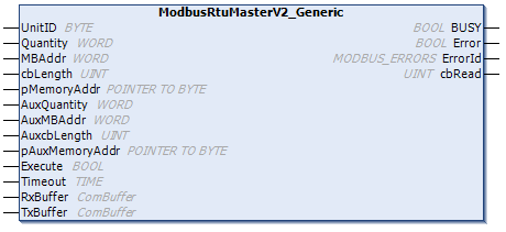
The function block ModbusRtuMasterV2_Generic implements a Modbus master that communicates via various serial interfaces (COM port, virtual COM port, EtherCAT Terminals, ...).
Due to the hardware-independent nature of ModbusRtuMasterV2_Generic, its use is somewhat more complex than that of the hardware-dependent function blocks ModbusRtuMasterV2_PcCOM, ModbusRtuMasterV2_KL6x22B, ModbusRtuMasterV2_ KL6x5B. All function blocks offer the same ModbusRTU functionality. However, the ModbusRtuMasterV2_Generic alone allows the use of virtual COM ports.
 | Connection to hardware via TF6340 TwinCAT 3 Serial Communication (license required) The data structures required to link to the communication port must be instantiated separately. The data structures of type ComBuffer present at this function block are data buffers for decoupling the hardware-dependent background communication. This background communication must be implemented via corresponding function blocks (SerialLineControl, SerialLineControlADS) of the Tc2_SerialCom PLC library, for which this PLC library must first be integrated in the program. The license for TF6340 TwinCAT 3 Serial Communication is also required. |
The function block is not called in its basic form, but individual actions of that block are used within a PLC program. Each Modbus function is implemented as an action.
Supported Modbus functions (actions)
- ModbusMaster.ReadCoils
Modbus function 1 = Read Coils - Reads binary outputs (coils) from a connected slave. The data is stored in compressed form (8 bits per byte) from the specified address
pMemoryAddr. - ModbusMaster.ReadInputStatus
Modbus function 2 = Read Input Status - Reads binary inputs from a connected slave. The data is stored in compressed form (8 bits per byte) from the specified address
pMemoryAddr. - ModbusMaster.ReadRegs
Modbus function 3 = Read Holding Registers - Reads data from a connected slave.
- ModbusMaster.ReadInputRegs
Modbus function 4 = Read Input Registers - Reads input registers from a connected slave.
- ModbusMaster.WriteSingleCoil
Modbus function 5 = Write Single Coil - Sends a binary output (coil) to a connected slave. The data must be ready to send in compressed form (8 bits per byte) from the specified address
pMemoryAddr. - ModbusMaster.WriteSingleRegister
Modbus function 6 = Write Single Register - Sends a single data word to a connected slave
- ModbusMaster.WriteMultipleCoils
Modbus function 15 = Write Multiple Coils - Sends binary outputs (coils) to a connected slave. The data must be ready to send in compressed form (8 bits per byte) from the specified address
pMemoryAddr. - ModbusMaster.WriteRegs
Modbus function 16 = Preset Multiple Registers - Sends data to a connected slave
- ModbusMaster.Diagnostics
Modbus function 8 = Diagnostics - Sends a diagnostic request to the slave with a user-specified function code (subfunction code). Since this function does not address a memory, the function code is transferred in the data word
MBAddr. Any data required for the function is included inpMemoryAddr.
Supported Modbus functions (actions) of the MasterV2 function blocks
- ModbusMaster.ReadWriteRegs
Modbus function 23 = Read/Write Multiple Registers - Sends the data specified via the Aux parameters to a connected slave and receives data from the slave at the same time. The received data is stored at the address specified by pMemoryAddr.
- ModbusMaster.UserReadWrite
Universal user telegram - The Modbus function code is specified by the user in the first byte of specified data (pMemoryAddr). With this function the user is able to send a Modbus telegram with any function code. Any data received from the slave is stored at the address specified by pAuxMemoryAddr.
 Inputs
VAR_INPUT
    UnitID      : BYTE;
    Quantity    : WORD;
    MBAddr      : WORD;
    cbLength    : UINT;
    pMemoryAddr : POINTER TO BYTE;

    AuxQuantity    : WORD;
    AuxMBAddr      : WORD;
    AuxcbLength    : UINT;
    pAuxMemoryAddr : POINTER TO BYTE;

    Execute     : BOOL;
    Timeout     : TIME;
END_VAR
Name | Type | Description |
|---|---|---|
UnitID | UINT | Modbus station address (1..247). The Modbus slave will only answer if it receives telegrams containing its own station address. Optionally, collective addresses can be used for replying to any requests. Address 0 is reserved for broadcast telegrams and is therefore not a valid station address (see UnitID) |
Quantity | WORD | Number of data words to be read or written for word-oriented Modbus functions. For bit-oriented Modbus functions, Quantity specifies the number of bits (inputs or coils). |
MBAddr | WORD | Modbus data address, from which the data are read from the end device (slave). This address is transferred unchanged to the slave and is interpreted there as data address. |
cbLength | UINT | Size of the data variable used for send or read actions in bytes. cbLength must be greater than or equal to the amount of data transferred as determined by Quantity. For word accesses, for example: [cbLength >= Quantity * 2]. cbLength can be calculated with SIZEOF(Modbus data). |
pMemoryAddr | BYTE | Memory address in the PLC, calculated with ADR (Modbus data). For read actions, the read data are stored in the addressed variable. For send actions, the data are transferred from the addressed variable to the end device. |
AuxQuantity | WORD | Additional parameter which is only used for read/write functions, see ReadWriteRegs/UserReadWrite |
AuxMBAddr | WORD | Additional parameter which is only used for read/write functions, see ReadWriteRegs/UserReadWrite. |
AuxcbLength | UINT | Additional parameter which is only used for read/write functions, see ReadWriteRegs/UserReadWrite |
pAuxMemoryAddr | BYTE | Additional parameter which is only used for read/write functions, see ReadWriteRegs/UserReadWrite |
Execute | BOOL | Start signal. The action is triggered by a rising edge at the Execute input. |
Timeout | TIME | Timeout value for waiting for a response from the addressed slave. |
 Inputs/outputs
VAR_IN_OUT
    RxBuffer    : ComBuffer;
    TxBuffer    : ComBuffer;
END_VAR
Name | Type | Description |
|---|---|---|
TxBuffer | Buffer with send data for the serial hardware being used. This data buffer is never directly written or read by the user, but only serves as a buffer for the communication blocks. The background communication must be realized via corresponding function blocks of the Tc2_SerialCom PLC library. | |
RxBuffer | Buffer into which received data is placed. This data buffer is never directly written or read by the user, but only serves as a buffer for the communication blocks. The background communication must be realized via corresponding function blocks of the Tc2_SerialCom PLC library. |
 Outputs
VAR_OUTPUT
    BUSY    : BOOL;
    Error   : BOOL;
    ErrorId : MODBUS_ERRORS;
    cbRead  : UINT;
END_VAR
Name | Type | Description |
|---|---|---|
Busy | BOOL | Indicates that the function block is active. Busy becomes TRUE with a rising edge at Execute and becomes FALSE again once the started action is completed. At any one time, only one action can be active. |
Error | BOOL | Indicates that an error occurred during execution of an action. |
ErrorId | MODBUS_ERRORS | Indicates an error number in the event of disturbed or faulty communication. |
cbRead | UINT | Provides the number of read data bytes for a read action. |
Requirements
Development environment | Target platform | PLC libraries to include |
|---|---|---|
TwinCAT v3.1.4024.0 | PC or CX (x86, x64, Arm®) | Tc2_ModbusRTU (>= v3.5.6.0) |